By Tony Cullen
COMPONENTS LIST
1x galvanized tow coupling
4x high-tensile steel zinc-coated coupling bolts
1x 2000 kg- rated high-tensile steel safety chain and shackle
Hub and stub set
2 x 330 mm rim wheels
Springs Kit
1000 kg multi-leaf springs, spring, slippers, spring hangers, bolts and nuts
4x U bolts, 2 galvanized U-bolt plates
6x tail gate hinges, 6 hinge pins 4 bolt-on antiluce tailgate toggles
2x toggle eye plates
2x tail-light assemblies
2x galvanized mudguards Plug and plug holder
WOF/Road tax holder
STEEL CUTTING LIST
RHS = rectangular hollow section iron
Main frame
40 x 40 x 3 mm RHS
2 @ 1800 mm (frame sides)
2 @ 1130 mm (frame ends)
Cross members
40 x 40 x 5 mm angle iron
2 @ 1130 mm
Drawbar
65 x 35 x 3 mm RHS
2 @ 1800 mm (drawbar arms)
Support plate
front of drawbar 50 x 5 mm flat 1 @ 150 mm
Coupling plate
80 x 10 mm flat – 1 @ 250 mm
Axle
50 x 50 x 5 mm RHS 1 @ 1300 mm
Mudguard supports
40 x 40 x 1.6 mm angle iron 4 @ 250 mm
Angle mounts
25 x 25 x 3 mm angle iron 4 @ 350 mm
Side rails
25 x 25 x 3 mm angle iron
2 @ 1795 mm (sides)
4 @ 400 mm (end supports) 40 x 40 x 1.6 mm angle iron 4 @ 400 mm (middle supports)
Tail gates
25 x 25 x 3 mm RHS 2 @ 1200 mm
Tail light full-width support
40 x 5 mm flat iron
2 @ 130 mm
2 @ 120 mm
40 x 40 x 3 mm angle iron
1 @ 1210 mm
Plywood
Between 5-ply 12 mm to 7-ply 17 mm tanalised C-D grade seconds
1 @ 1760 mm x 1200 mm (deck)
2 @ 1200 mm x 280 mm (tail gate boards)
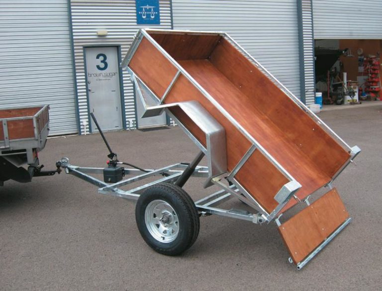
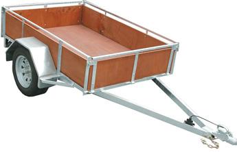
With minor variations, I have built a standard 1200 mm x 1800 mm (6ft by 4ft ) domestic trailer with a solid frame of rectangular hollow section (RHS) mild steel.
The frame is braced by angle-iron cross members and has a sturdy, ply wooden deck. It’s best to use not less than 5-ply 12 mm minimum — in this case we have used 7-ply 17 mm. With minor variations, I have built a standard 1200 mm x 1800 mm (6ft by 4ft ) domestic trailer with a solid frame of rectangular hollow section (RHS) mild steel.
Getting first corner right.
Check frame for square.
The frame is braced by angle-iron cross members and has a sturdy, ply wooden deck. It’s best to use not less than 5-ply 12 mm minimum— in this case we have used 7-ply 17 mm. Welding is the key to putting together the frame, and a cutting list of the lengths of steel is provided.
The principal trailer components — coupling, safety chain, mudguards, wheels and so on, as outlined in the components list—can all be bought from regular suppliers. Full assembly instructions come with the components. A crucial step in building the trailer is to get the axle stub straight, otherwise your tyres will chop up as they run. You could use a jig of angle iron to get this straight or, as I did, simply hold the axle stub firmly against the bottom and one side of the box section axle to ensure it is square. There must be good welds on the axle stub. The plate where the coupling is bolted must be strongly welded to the drawbar for safety reasons when towing. If you have any doubt about your welding experience, have an expert do the coupling plate weld.
Clamp to bench.
Tack-weld cross members.
Clamps are used every step of the way and it will speed up the assembly of the trailer if you pre-cut all material and mark all the pieces with top, bottom and sides, and front and back.
While home workshop owners are exempted from having a New Zealand Standard (NZS) 4711 welding certificate when making a domestic trailer, the welding is required to be up to the joint Australian New Zealand AS / NZS 1554 standard (in part originally NZS 4701). For a Warrant of Fitness, the welding is checked thoroughly visually on a new trailer.
Frame lay up
Chalk a straight line on the ground or bench, and lay up the side and back of the frame. Check on the inside measurement with a square. The first right-angle between the side and back is important as other measurements depend on this first corner. Tack weld the first corner on its own.
When all four RHS sides are laid out, tack weld. I have made the trailer an extra 10 mm wide (1210 mm = 1130 mm cross-frame angle iron + 2 x 40 mm width of RHS sides). If the plywood sheet is not exactly square, it allows room to make it easier to drop in. Check the frame is square by the diagonals. It is harder to do on the floor, so next I clamp the tack-welded section to the bench and tap it straight (checking with the square).
At this stage you are working with the frame upside down. It is easier to place the heavy drawbar resting on the frame, than to hold the lengths up under the frame. While the trailer is upside down, I do the frame and drawbar, springs, axle, hubs and wheels. Then I turn it over to do the mudguards, mounts for the side bars, front and tailgate and lights.
Check springs are square.
Let spring come through slipper.
.
Cross members
Drill a hole on one side of the angle iron near the end for the lights cable to go through. Clamp small pieces of metal under the frame as it sits, and rest the angle-iron cross members on them. I tack weld the two cross members at equal distance from the ends of the trailer frame and from each other, in this case at 600 mm. Angle iron is cheaper than box section and does the job. Keep the angle-iron cross members flat in line with what will become the top of the RHS frame, as the wooden deck will be screwed to them.
Springs
The rating of the springs is deter-mined by the number of leaves. The spring here is strong enough to hold the axle unit and we have used springs with a weight rating of up to 1000 kilograms or one metric tonne. Do not overload when filling the trailer with things like builder’s mix. Set the springs, with their centre pole for the axle over the 900 mm centre of the 1800 mm side frames.
Centre the axle so the 40 kg weight of the drawbar is a bit forward, otherwise the trailer would rattle when travelling empty. You need to know where the springs are placed first, in order to locate exactly where the drawbar sits back on the side beam. Check that the springs are square. Now place the bolt frame and slippers for the springs. Allow 50 mm of spring to come through at the back of the slipper. If the spring compresses suddenly, say, bumping over a gutter, it will pop out of the lens of the slipper. Then you have to unbolt it to put it back. Tack weld both the front attachment to the beam where the springs are bolted into place and the slipper at the back.
Drawbar
The A-shape of the drawbar is stronger than a single, straight steel drawbar. The rule of thumb is not to get it too short because then it is too hard to reverse the trailer. The minimum length should be between 1200 mm and 1500 mm from the front cross member to the tow coupling. I have decided on a drawbar of RHS beams 1800 mm long overall.
Centre drawbar.
Place the drawbar back towards the springs, so you can have welds on both the front beam and side beams. To get the drawbar centred, mark the 605 mm centre point in the 1210 mm width at both ends. Take a string from the back frame and across the centres to the tip of the drawbar to get the drawbar central. Butt the drawbar together on the centre mark.
The drawbar sides should be flush with the side beams where it is to be welded.
The length of the drawbar should now be 1140 mm from the drawbar tip to the front beam. By the time the coupling plate is welded on the drawbar, the total length will be around 1300 mm. Tack weld the back of drawbar to the beams.
Tack-weld drawbar to front beams.
Put skip mount on coupling plate.
Coupling plate
Drill holes in the coupling plate, using the bolts placed through the coupling for marks.
Clamp the coupling plate to the drawbar underneath, leaving the bolt holes clear. (The coupling plate is thus topside, while you are working on the underside of the trailer.) Take the string to the end of the plate—line everything up on the halfway mark. Tack weld the cou-pling plate onto the drawbar. Tack weld the drawbar onto the front beam. Put a skip mount onto the coupling plate. It prevents the drawbar digging in when it drops onto the ground. This also strengthens the coupling plate.
Tack weld it. Drill a hole near the front of the drawbar for the bolt of the safety chain.
Before I move the frame from the bench, I fully tack the box section joints. Turn the frame over and suspend it on two saw horses or similar.
Turn frame over.
Measure correct width for axle.
Axle stub positioned.
Axle
I then put the springs back on and place the axle to know where to drill a hole in the axle for the springs locator. To get the correct width for the axle RHS, put the wheel with the tyre onto the hub and axle stub, and place it in the box section. The tyre should be 50 mm from the side rail.
Measure the width across the trailer from spring centre to spring centre. The trailer frame is 1210 mm wide, the springs are 45 mm wide. So from locator pin to locator pin in the centre of each spring should be 1165 mm. On one half of the axle, drill a locator hole for the pin at 582 mm from the axle centre. Place the axle and measure to the other locator pin to drill the second locator hole.
Stub axle and spring locator holes on different faces.
Weld in stub axle.
.
Put the axle stub in the wheel. Put it in the box section with a 50 mm space to the tyre, Mark the stub with a chalk line where it emerges from the box section. When I took the stub axle out, I found the chalk line was at 70 mm from the inside end of axle stub. As I drilled a hole at 50 mm from the end of the box section (weld material enters here to hold the axle stub in place) this allows for another 20 mm of stub inside the box section for added strength. Make sure you turn the box section to drill a different face from the face where the spring lo-cator hole is found.
Push in the stub axle to the chalk mark and hold it in place. Hold the stub axle firmly while tack welding (I use a jig but you can hold it with your hand).
Hold the stub square and hard on bottom and flush against the side– you can tell when it’s firm and square against the side of the box section.
With axle stub in place, if you want to check the squareness of the hubs, assemble both and do measurements all around the circumference. The four positions should be the same and I found that the 1480 mm distance checked on every quarter of the hub face. I do this measuring when the stub axle is tacked only (in case of alteration). Now weld the axle stub in by first filling the hole in the box section. When welding the axle stub, you can leave the nut on the hub to protect the thread. Weld the end of the axle box section as per the instructions for the components. The other hole in the axle is for the spring locator.
Now drill two or three 4 mm or 6 mm holes in the axle and all the closed cross-section members to al-low for breathing during galvanizing. The drawbar and side members of the frame are open-ended cross-sections, the front and back middle members normally close-ended sections.
Place the axle on the locator pins and bolt it on to the springs by U bolts supplied. I put the axle on top of the spring to get the trailer lower which I prefer — it looks ugly if it is sitting up at an angle to the car. (The Code of Practice for Light Trailers Standard NZS 5467:1993 3.3.1 refers to a “properly set-up” trailer).
Check distance from hub face.
Locate axle and bolt onto springs.
Put together axle assembly.
Mudguards
Put together the axle assembly to make sure it all fits and to get the height of the mudguards. Put the hub and wheel on. Put 80 mm clearance between tyre and mudguard top—enough room so that when the weight on trailer depresses the springs so the mudguard does not hit the top of the tyre. I use a block of wood on the tyre to set the gap and put a jack under the lifted trailer to stop the wheel turning. Measure 900 mm along the centre of the side beam to centre the mudguard.
Measure gap for mudguard.
Centre on beam and square mudguard.
Square up the mudguard mounts are pre-cut and pre-drilled. Clamp and weld them, and the angle mounts, underneath the side beams for strength, rather than butt weld them sitting against the side beams. Always check that the mounts are square to the beam. Angle mounts give strength and protect the mud-guards — people driving around may run into things with the side of the trailer, or might stand on the mudguards if there are no angle mounts.
Clamp the mudguard to the mount so it is flush against the side rail.
Drill through the mount holes to mark the mudguards. Dill them on the bench and bolt back on.
Attach mudguard angle mount under beam.
Keep mounts square.
Tack weld uprights.
Side Rails
Use the 3 mm-thick angle iron for the four corner uprights, and 1.6 mm-thick angle iron for the up-rights along the side. Pre-drill holes in the back and front uprights for the toggle bolts which will fasten the gates. I worked the height out in conjunction with the 30 mm long hinges that come in the trailer components.
The tailgate and front gate will have three hinges welded and suspended from the back and front top rail. The side boards will be 300 mm from deck, but it’s not critical for the toggle to be 300 mm. I pre-drill the toggle hole anywhere below the 300 mm top line. Now weld the uprights along the sides onto the beams. I do the back corner first, making sure the flange of the angle iron is outside to receive the top rail. Clamp and check it’s square. I have found a magnet square handy. Then tack weld the back upright.
Do the same with the front upright, then measure the angle iron top rail to see that it fits. The top bar flange is placed so the side uprights can fit in underneath.
Clamp the top rail and tack weld it. You could use box section instead of angle iron but it comes down to cost. When you place the timber sides, leave a gap so you can tie off on the top bar when using the trailer.
Next I place the uprights along the side. The distance of the uprights from the end of each side doesn’t matter as they are only to attach the side boards to. I locate the uprights on the mudguard mounts to add strength. Check they are square, clamp and tack weld.
Sides in place
Mark cut on hinge after clamping toggle strap.
Gates
The front gate and tailgate are built in the same way. The top rail is 25 mm RHS, and there are three hinge straps. The outer hinge straps have the toggle strap welded to them. The middle hinge strap is placed at the 600 mm centre of the 1200 mm rail. Both toggle and hinge straps are available as ready-made components, although I make my own.
Put the toggle in the outside up-right so you can measure the gates against it. Clamp the toggle strap to the upright and measure where the hinge will be cut. I measured 360 mm from the top of the upright to the top of the deck, less 25 mm for the width of the top rail, and cut the hinge at 335 mm.
Check how far down the toggle strap is on the upright and on the hinge—in my case, 45 mm—and how far the outer hinges will be in from the side when attached to the toggle strap. Square the hinges against the rail and clamp them on the bench. Tack weld the top of the hinges to the inside of the rail and tack weld the toggle straps to outer hinges.
Hinges
Fit the tailgate, making sure the toggle is in middle of hole in the toggle strap and will slide open off the toggle easily. Clamp the hinges to the frame at the bottom. I like to make sure the hinge pins all point in the same direction, so that the gate can be slid off (when you need to have open trailer front or back for long timber, for example). Grind away weld obstructions on the side-mounted uprights to allow the hinge pins to fit smoothly across, prior to welding them. Put in the toggle and clamp on the toggle strap. Tack weld the hinge pins to the frame.
The straps to support the angle iron frame that holds the number plate and lights is butt-welded flat to the side frame. Underneath the trailer tailgate, tack weld the angle-iron cross bar onto the metal straps. The strap for the light assembly sits inside the flange of the angle iron and on top of the box section.
To create tie-ons for ropes securing loads, bend small pieces of rod in a vice and weld two or three along the side frames. Weld two small sections of pipe about a metre apart and along the inside of the side frames for the light cable to run from drawbar to the back of the trailer. I now round off the sharp edges of the frame with the grinder.
Check how far toggle strap is down hinge.
Tack weld toggle strap to hinge strap
.
Galvanizing
It pays to pre-drill as many holes as possible before the galvanizing. These include holes in the hinge straps and holes in the angle-iron supports for the side boards.
Before galvanizing, the trailer must be disassembled. Take off the wheels, mudguards, axle, springs, gates and coupling. Solidly weld all the tack welds you’ve made in every joint. This is obviously for safety. But also, when you send the trailer frame, gates and axle to the galvanising bath, you need to have the welds fully enclosed. If you send it only tacked, rust gets in the gaps and weeps out in the metal when it is dipped in acid first to pickle it, and this is unhelpful to the galvanising
If you painted the trailer instead of galvanizing it, you wouldn’t get deep inside the box section to stop rusting in there. You can paint the frame after galvanizing, but there’s a lot of fuss with primer and preparation.
When the trailer is back from galvanizing, use a drill to clear the box-section vent holes drilled originally for safety during galvanizing. Drill out other holes in the spring holders and in the angle iron cross-mem-bers pre-drilled before galvanizing. Check the coverage of the galvanizing, especially on the welds. Rust can occur on a weld that has been sitting in the rain after galvanizing, if there is an air lock not properly covered by the weld. The wiring clip-barrels and tie-ons (pieces of bent rod) that were welded to the trailer frame should also be well covered with galvanizing. To cover any gaps in the galvanizing, you can use spray-on cold galvanizing zinc spray from a can. Follow the instructions.
Clamp hinges to bottom of frame.
Trailer ready for galvanizing.
Hot-dip galvanizing.
Tailgate cutting
Use the offcuts from the deck ply-wood to make the front and end tailgate boards and side boards. There should be enough ply left, if you make the boards 280 mm high. This height leaves a gap at the top between the boards and top rail for tying off tarpaulins and loads. Have the boards cut and ready to check the placement of the deck back and front.
Deck
Place the frame on sawhorses or similar. While the deck is off, run the cable through the draw-bar down one side and through the wiring barrels. Run a second wire across the back. Join them later when you wire up the lights. Leave a bit of extra wire lead at the front—I allow a metre at the base of the front tail gate so I don’t get front and back mixed up. They are probably not exactly identical gates. Check with the gates placed on to make sure you will cut the ply deck short enough. Remember the frame was built 10 mm wider than the sheet of ply, in case the ply was out of square.
With the ply in the frame, mark it underneath at the ends where you will trim it shorter to allow the gates to close.
Now take the deck off, or use an air hose, and clear the swarf from the cross-members before you screw the ply down. The swarf, or iron fillings drilled out from the steel, will raise the deck and let the water in under the wood, where it will stay and cause rust. Trim the deck ends to size. Plane the deck sides smooth.
Replace the deck and screw it on. You don’t need a lot of screws because the side boards hold the deck down.
Fit ply deck.
Gates back and front
Put on the tailgate and lock it in place with the toggles. The nuts that come with the toggles in the components are locking nuts, but you could use ordinary nuts with a spring washer.
Clamp the tailgate board in place so you can locate it correctly. There is a 12 mm wide gap already between the side of the tailgate and the side rail, but as the tailgate board butts up to sideboard, it will cover this.
Check with a piece of scrap offcut first. Drill through the hinge straps at 200 mm intervals into the tail-gate board. You could pre-drill these holes as I have done.
I would normally rivet on the tail-gates with 4 mm-head rivets at 250 mm spacing as it looks neater and is quicker. For the 17 mm 7-ply deck we would have needed rivets 30 mm long in total. With rivets not available, I used 6 mm-head coach bolts with spring washers. I put two coach bolts in each hinge strap.
Drill from underneath.
Locate gates.
Side boards
Clamp the 1760 mm x 280 mm-high side boards inside the angle-iron side board uprights, leaving a gap for tie-offs to the rail. Drill through the uprights or through pre-drilled holes into the side board. (21) In-stall two coach bolts in each upright with the round heads on the timber. Plane the edges of the timber on the corner angle for a smooth fit and neat finish.
Rivets are quicker to insert and look tidier, but could shake loose. If you have used bolts as I did, check them from time to time in the life of the trailer because they can work loose.
Wiring to back.
Ensure sides are flush.
Springs and axle
Some makers don’t galvanize the supplied springs because they can go brittle at the high temperatures used in galvanizing. It’s not crucial for a domestic trailer, but they should be galvanized for a boat trailer going into salt water. Locate the springs in the slippers and in the spring slots and bolt either side. Ensure there is room at the mudguard bracket when the spring compresses under a load and slides back in the slipper. For extra strength, I welded the mudguard support under the frame (not butt-welded against the frame) but I had to cut the angle iron with a grinder to give the spring room to move. Then I repaired the galvanizing with a cold galvanizing, zinc spray. The axle has been hung by one end when being dipped in the galvanizing tank, so the thread at that end should not be clogged. But, after galvanizing the trailer sits around and the untreated part rusts. Clean the thread with a file, wire brush and emery tape sandpaper. Clear the galvanizing from the thread on the other end of the axle. Make the hole for the split pin clear.
Place the axle on the spring locators and bolt the axle in place with the supplied U-bolts and plates. Now assemble the axle hubs according to the instructions that come with the components. Check that the nut and bearings go on before assembly of the whole thing. Check that the stainless steel ring goes on and that the seals are in. The hub goes on filled with grease. Make sure you get plenty of grease in the bearings and inside the hub. Complete the assembly of the hub and bearings as per instructions.
Place axle.
Drill tailgate hinges.
Wheels, mudguards
Put the wheel on to get the adjustment right. For the Warrant of Fitness, the bearings must hold the wheel firmly. Test whether there is play in the bearings or they are too tight by trying to wobble the tyre, holding the top and the bottom. Put the split pin in when the play is out of the bearings. Then hammer the bearing cap on. Tighten nuts on the hub loosely at first. The tyres for this size trailer should be 175 / 70 R13. When working with the mud-guards, I mark them Right Front and Left Front. This is because after you measure the mudguard mountings, they are welded to fit where you have measured them. Bolt the mudguards on.
Wiring
Trailer lamps that come with the trailer components kit should have a stop lamp, indicator and clear lens to the side for a white light onto the number plate. I rivet each lamp backing to the metal strap under the trailer frame at the back, but they can be bolted or screwed on.
I have used one of the standard plugs to the towing vehicle, a 7-pin connector. The New Zealand Standards Code of Practice for Light Trailers describes the colours and circuits for the 7-pin connectors as: left-hand turn, yellow; reversing signal, black; earth return, white; right-hand turn, green; service brakes, blue; stop lamps, red; rear lamps, clearance, side marker lamps, brown. For the wiring, I use a standard 5-core electrical cable so I left out the connections for the auxiliary / braking and reversing light wires.
I have fed the cable from the towing connection at the front of the drawbar, through the drawbar and down the right-hand side of the trailer (left and right are the positions when looking at trailer lights from the back towards the front). Now you need to join wires from the cable across the back, coming from the left -hand light, with the wires from the cable from the front, to the right-hand light. Put the bulbs in. Make sure you don’t trap wires with the metal separator inside the lens. Place the covering lenses over the lamps.
Drill holes for the number plate in the frame next to the back light. The un-coloured lens at the side of the lamp should allow the light to shine clearly on the number plate. To hold the connector plug for the car at the front of the trailer, drill into the draw bar and rivet or screw on the plug holder.
Wire up connector.
Coupling
The coupling is bolted on with high-tensile zinc-coated bolts to the weld-ed coupling plate. Screw into the drawbar hole previously drilled the high-tensile bolt that comes with the chain. A supplied chain should have a weight rating which is twice that of the rating for the weight of the trailer or the springs (e.g. this trailer with 1000 kg weight-rating for the springs, has a safety chain with a rating of 2000 kg).
Bolt tow coupling on coupling plate.