By Terry King
So far we have begun to get acquainted with the Arduino and IDE, the “sketches” or programs that make it work, and we have got it working blinking an LED on and off. In this article we will delve a little deeper preparatory to diving right in with a fully edged project with some real- world applications in the next issue.
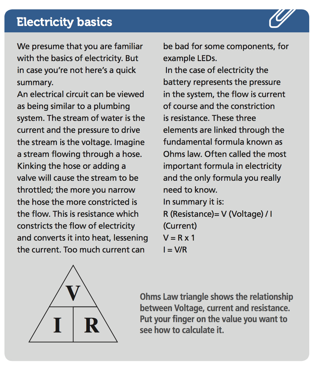
We have set up a page on The Shed website to hold all the arduino sketches we are discussing here. You can simply copy and past them into your own IDE. To begin you need to understand a bit about electricity (see panel) and how that translates into the digital scheme of things.
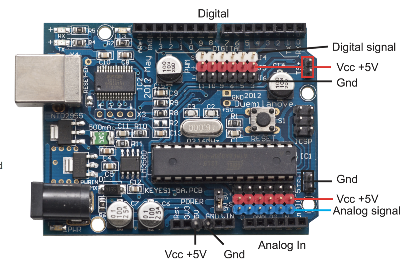
t’s easy to connect many things to YourDuino. There are many pins for Ground and +5V. The two pairs of pins on the right side are handyfor connecting to your breadboard. Three-pin cables with the standard pattern of Ground- Voltage-Signal (usually Black-Red-White) plug right in.
Circuit diagrams
GND, INPUT, OUTPUT, etc.
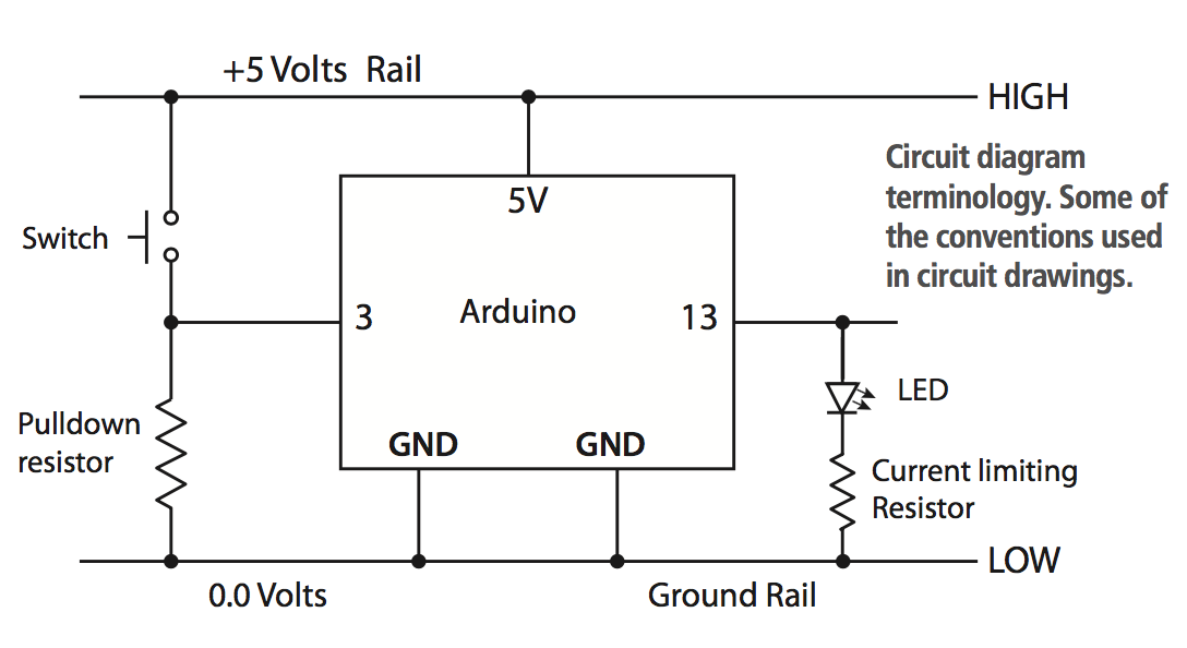
Arduino is powered by +5.0 Volts of DC (Direct Current).We show the +5.0 Volts connected HIGH on the top. Look closely at the YourDuino nd the PIN marked “5V”. That’s the one +5.0V power is connected to. Where does it come from? In the rst place it comes from the USB cable from your computer to Arduino. There is provision for a dedicated power supply, however. We show GND (Ground) connected LOW on the bottom of the Arduino. Find the Pin marked “GND”. There are actually 3 “GND” pins.
Rails
The parallel lines of +5V (HIGH) on the diagram, and GND (LOW) on the diagram are called Rails. Like railroad rails across the top and bottom. Almost everything that happens on Arduino is between the +5V (High) rail and the GND (Low) (0.0V) rail.
Digital signal
You will hear Digital signals described three or four ways: but 0, OFF and LOW mean the same thing. And 1, ON and HIGH mean the same thing. When a Pin (or wire or connection) changes from 0 to 1, or 1 to 0, we say it is a SIGNAL, like someone raising or lowering a ag. Each signal is referred to as a BIT (a Binary InTeger) A bit is a number which has only two possible values: 0 (Low) and 1(High).
Bits & Bytes
A group of 8 bits is called a BYTE. 1024 bytes (8192 bits) is one Kilobyte(It’s based on 2 to the power of 10 (210). 1048576 bytes (2 to the power of 20) is 1 Megabyte (MB) and 1 Gigabyte (GB is 230.) Note that this convention is not the same as a kilogram which is 1000 grams. Output signals: An LED or Buzzer connected to an Arduino OUTPUT can “signal” you that something has happened. Input Signals: If you push a button that changes an INPUT, you “signal” Arduino that something should be done.
Time to hook real things up to those INPUTS and OUTPUTS. Take a couple of minutes to look at the Arduino board closely. All regular Arduino boards have the same overall size and the same long black connector strips across the top and bottom edges. These are female sockets that pins can plug into. Let’s look at the details. First the top connector: The sockets are numbered 0 to 13 from right to left. These are the DIGITAL INPUT/ OUTPUT connections. You can push wires or the pins on the end of wires into those “Black Holes” and connect them to many different devices. We then tell the arduino how to treat them: as Input (digital Read) devices or output (digitalWrite) devices.
Digital input
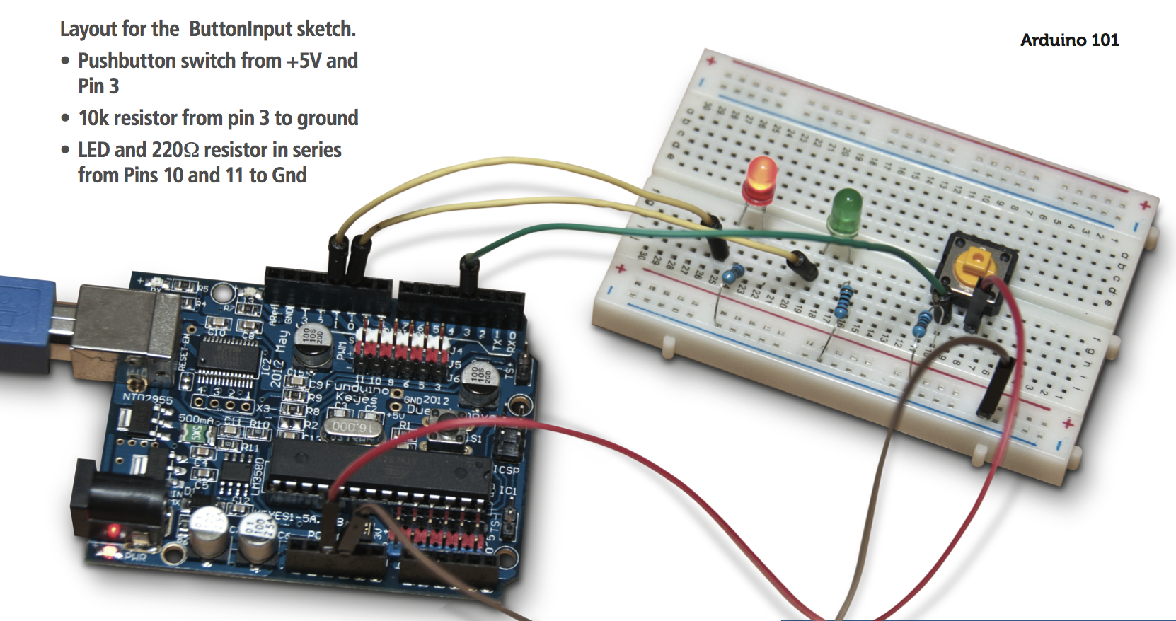
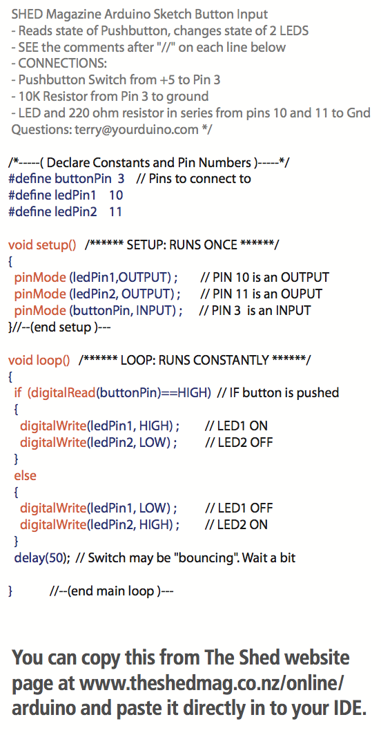
Our circuit diagram shows a very simple circuit using a pushbutton to control the outputs of two LEDs. Make up the circuit shown on your breadboard. The pushbutton switch causes the INPUT to change from LOW to HIGH, which is a “signal” to the arduino. Arduino can change the OUTPUT on one LED from LOW to HIGH, and the other from HIGH to LOW. Copy and paste the sketch into your IDE and load it. This sketch adds three constants: two LEDs on pins 10 and 11 and a new INPUT, the BUTTON on pin 3. This sketch introduces a new concept essential to all microprocessor and computer programs the “If” statement.
If statement
The “If” statement makes the computer ask a question and take an action based on the answer to that question. In this case we have asked it to digitalread the buttonPin and compare it to a reference. The == symbol is used when we need to compare a value against a reference you supplied (that’s what HIGH means). It returns an answer of either true or false. If TRUE then the program carries out the actions described in the curly brackets immediately following. If FALSE then it runs the instructions in the “else” condition. The else condition is optional the default is to do nothing and make no change.
Feel free to make additions to this sketch and try different combinations. Add more pushbuttons for example or more LEDS.
Resistors
You may be wondering what the purpose of the 10kΩ resistor connected to the GRD rail is. This is what is called a pulldown resistor. In this case it ties the output to ground when the button is open. Remove it and see how the circuit performs. Without the resistor the arduino gets no signal to the pin so it tends to pick up stray electromagnetic signals called noise and these can cause the pin to fluctuate between its two states rapidly and generate an inconsistent response. The resistor ties the circuit to ground with a high resistance when the circuit is open so the pin has a LOW signal rather than NO signal.
The lower resistance of the closed circuit (when the button pushed) will activate the pin high as more current will flow directly to the pin overriding the pulldown resistor. The switch will PULLUP the pin against the PULLDOWN resistor. These resistors are important in digital circuits. They can also be used as pullup resistors keeping the circuit high when open.
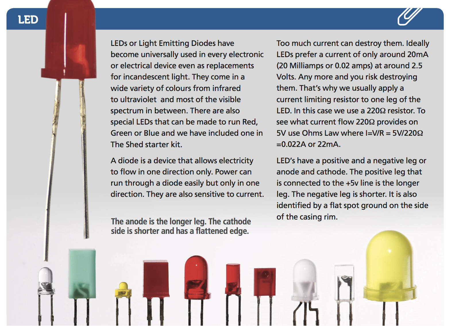
You will also notice the addition of the two 220Ω current limiting resistors for the LEDs (see LED panel). We didn’t need this previously because the Yourduino has one built in to Pin 13.
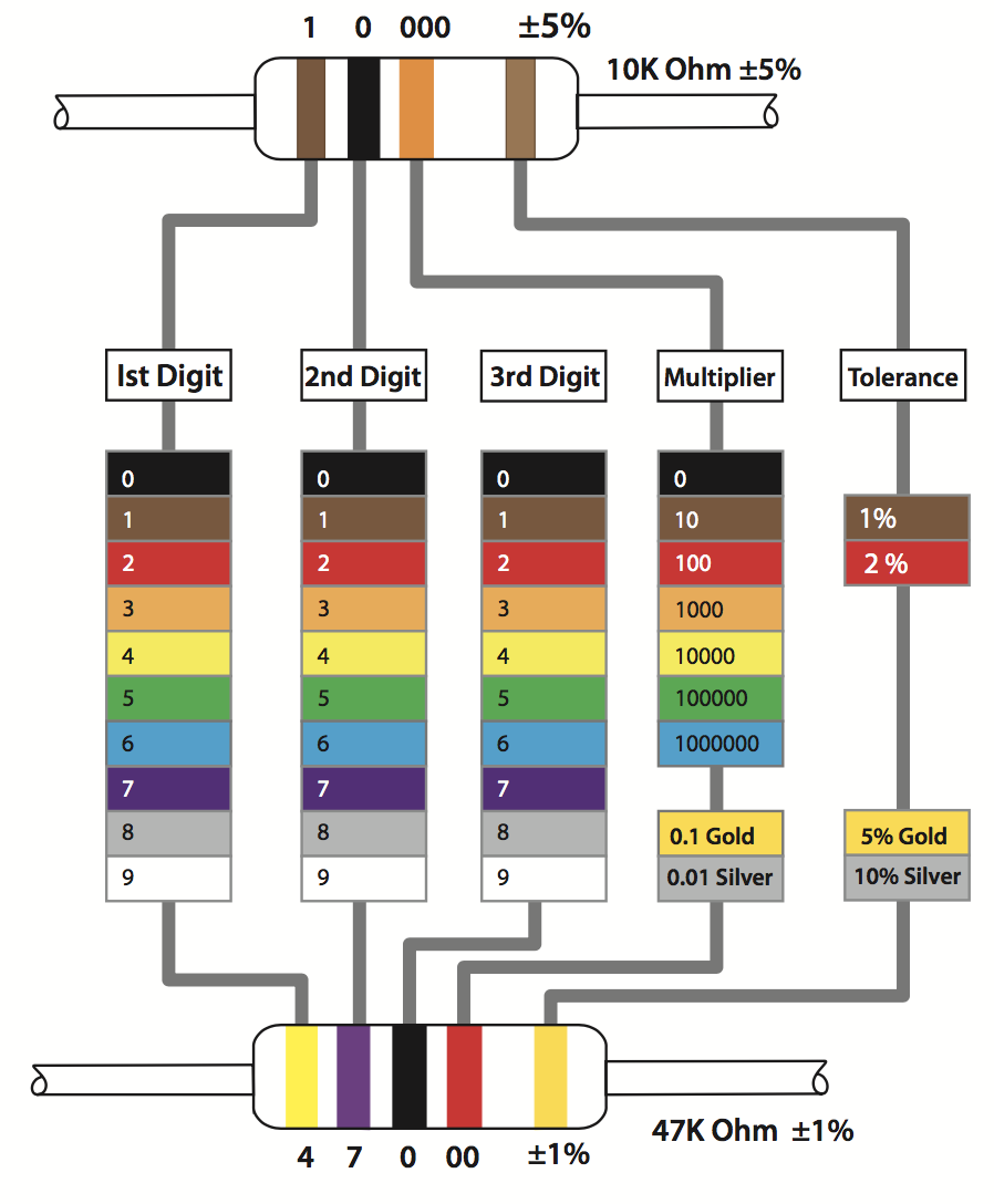
Resistors are the most common electronic component; they are also the simplest. They have one job to do and that is to restrict the flowofcurrent. Resistanceismeasuredin Ohms with the Ω symbol. They range in value from 1 ohm to megohms (MΩ). Resistors are non polar so they have no specific orientation. They are usually marked with coloured bands and these bands have a specific code. It’s worth knowing the code and you will probably get to know it with time especially the more common values. You can also check a resistor’s value with a multimeter set to read resistance but being able to read the code is a serious time saver. There is much more to know about resistors and how they operate in a circuit and Make:Electronics is a recommended source for more information.
RESISTORS COLOUR CODE
Most resistors have a colour code to represent their value. There are 4 or 5 coloured bands on the resistor. To one end is a stripe of either gold or silver usually alone. If you orient this to be on the right side then the first two bands from the left represent the value of the resistor. The third band indicates how many zeros to add orits exponent for those that know their maths.
Analog In
So far we have covered digital signals out (digitalWrite) and digital in (digital Read). But Arduino also has analog inputs. Analog inputs are far more common than digital (although that is rapidly changing). We have incorporated several into the starter kit. Digital has two values either on or off but analog has an in nite number of values. One example of an analog in the starter kit is the potentiometer. A potentiometer (or Pot) is a variable resistor.
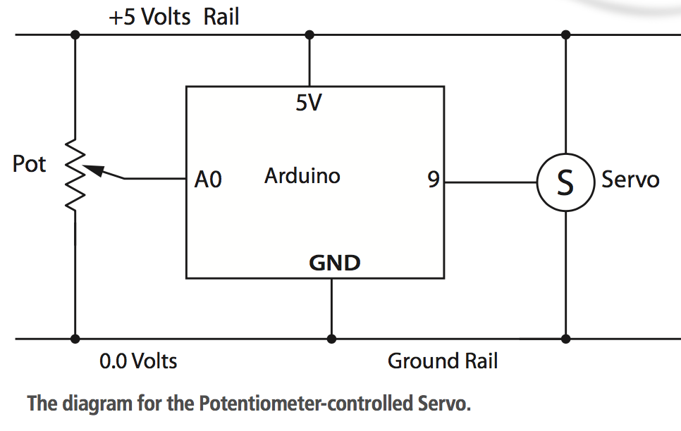
The Pot has three connections, the outer two left and right are connected to the +5V and GND respectively and the centre connection is the signal. From the schematic you can see that the pot is basically a surround of resistive material and a wiper that contacts it.
As we move the pot, the output voltage going to Arduino varies from 0 to 5 Volts and all the values in between. Arduino reads these as values from 0-1023 where 0 is the GRD and 1023 is +5V. In this sketch we will use the input signal from the pot to control a servomotor. A servomotor is motor that can move to any position through 180 ̊. They are widely used for controlling things like steering, for example, but any purpose that requires incremental operation of a mechanical device is suitable for a servo. The stepper motor in The Shed Start Kit has three wires running to a three- pin female connector. These three connections are GND (Brown) +5V (Red), and Signal (Orange) respectively. You will see on the Yourduino board that there are a number of three pin connectors in both the digital and analog connectors.
The digital connections in the top block are coloured white, red and black. The black is GDN, the red +5V and the white is the Signal. This is the connection for the three-pin connectors. If you have a different arduino you will have to improvise this connection on the breadboard.
Find the sketch called ServoPot in the sketch depository in The Shed website. Copy and paste it directly into your IDE. Set up the circuit as described on your breadboard and the arduino and upload the sketch to YourDuino. As you move the pot the servo should turn back and forth. What’s happening here? An Analog Input Device (the Pot) is feeding a varying voltage into an Arduino Analog input. The Arduino sketch is making decisions based on that value to send an Output Signal to the Servomotor. Arduino is reading the position of the Pot wiper scaling that into a digital signal and sending that signal to the servo. To ensure that the servo actually has time to move to the position there is a delay of 25 milliseconds before it reads again