By Mark Beckett
LCD for the Temp Controlled Relay
In the last issue we presented a project to create a temperature regulator. In this issue we will show you how to include an LCD that displays the highest and lowest temperatures, along with the current temperature. In the sketch I have also included a section that scrolls text, as a demonstration.
LCD
Liquid Crystal Displays (LCD) are constructed of layers with a liquid between the layers. When an electric current is passed, they align the crystals to either allow or block light, thereby forming recognisable characters or shapes. They feature very low power consumption with very high contrast, and come in a variety of forms, sizes, colours and response times. We are going to use a standard 16×2 LCD (16 characters x 2 lines), which are readily available and with the use of an Arduino library, can accept standard ASCII characters.
Using certain commands, we can control the placement of the characters, clear the display, and manipulate the characters that form feedback to the user.
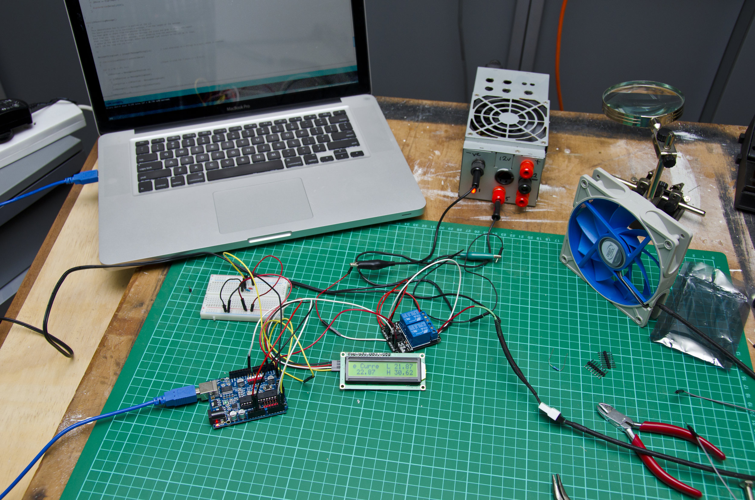
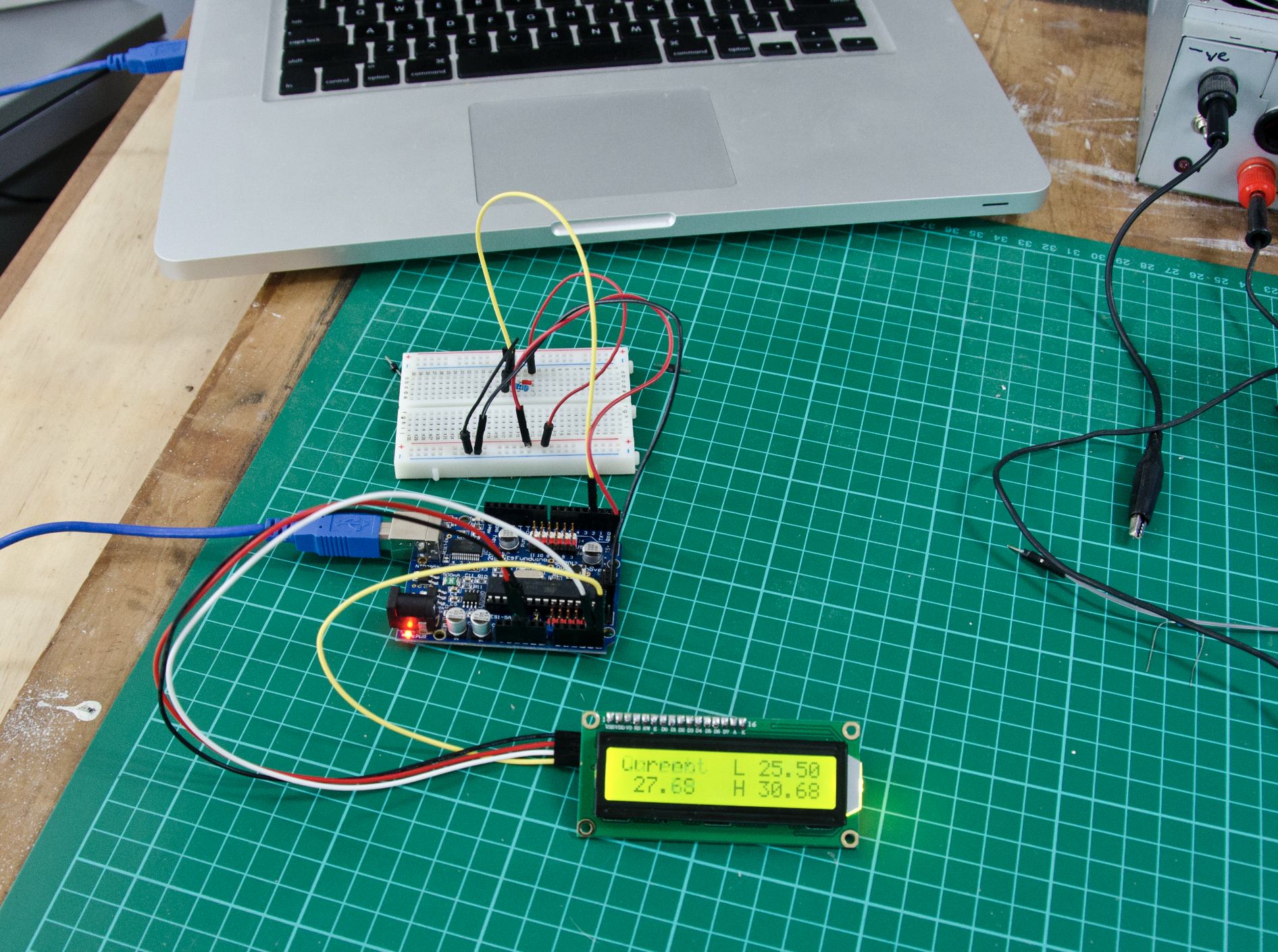
The layout for the standard LCD. Temperature sensor is on the breadboard to the left
Connections
The basic LCD needs power (+5 and GND), 4 data and 2 control lines. A backlight and a voltage for contrast control make the total = 10 wires. Recently I2C (I squared C but usually written as I2C) displays have become very cheap. These displays only need power and two wires to operate (total 4 wires). Most are simply a basic display with an additional board to convert the I2C data.
There is a difference in the library and the sketch for controlling the I2C device, and we have included both sketches for the standard LCD and an I2C one. The connection details and pin numbers for each are in the sketch for each type.
Setup
After the LCD is wired, the library needs to be initialised by the sketch to tell it how many characters and lines and more importantly, which pins on the Arduino to use for what purpose. For our basic display this is done by the line LiquidCrystal lcd(8, 9, 4, 5, 6, 7); which sets up the pins (RS, En, D4, D5, D6, D7), while lcd.begin (16, 2); tells the Library to start, using a 16 character by 2 line display. For the I2C displays, the library sets these to suit the display they are attached to, so download the correct library to match the display. A contrast voltage on lcd pin3 changes the amount of drive to the liquid.
This needs to be set in order to view the display. We use a 10k pot with one end connected to +5v and the wiper to lcd pin3 with the other end to end. Adjust until you see 32 blocks then adjust until they just disappear, at which point the displayed information should be visible. To fit the basic LCD to the temp relay layout we will need to move the relay control pins to D10,11 as the LCD is 8 and 9.
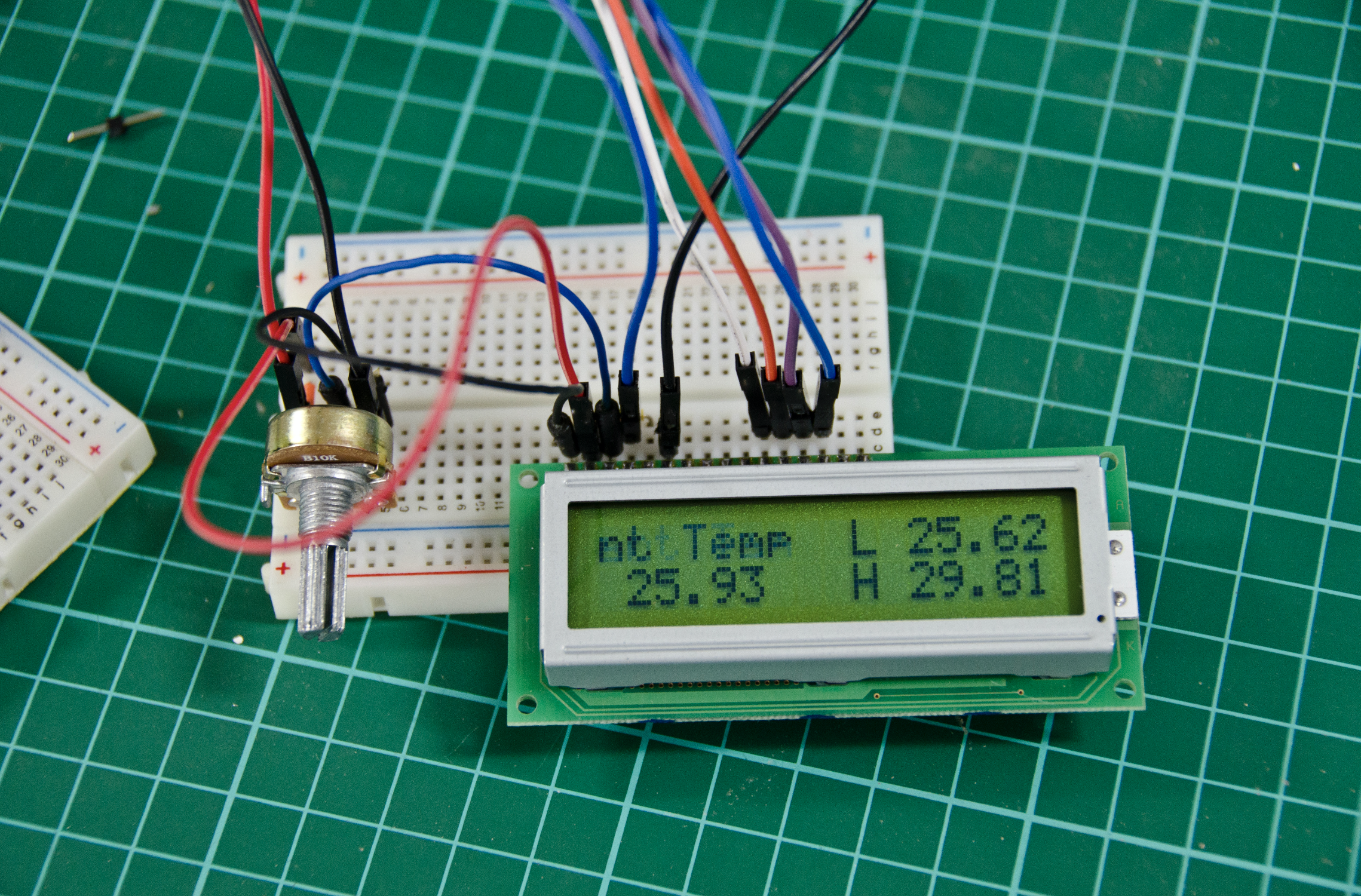
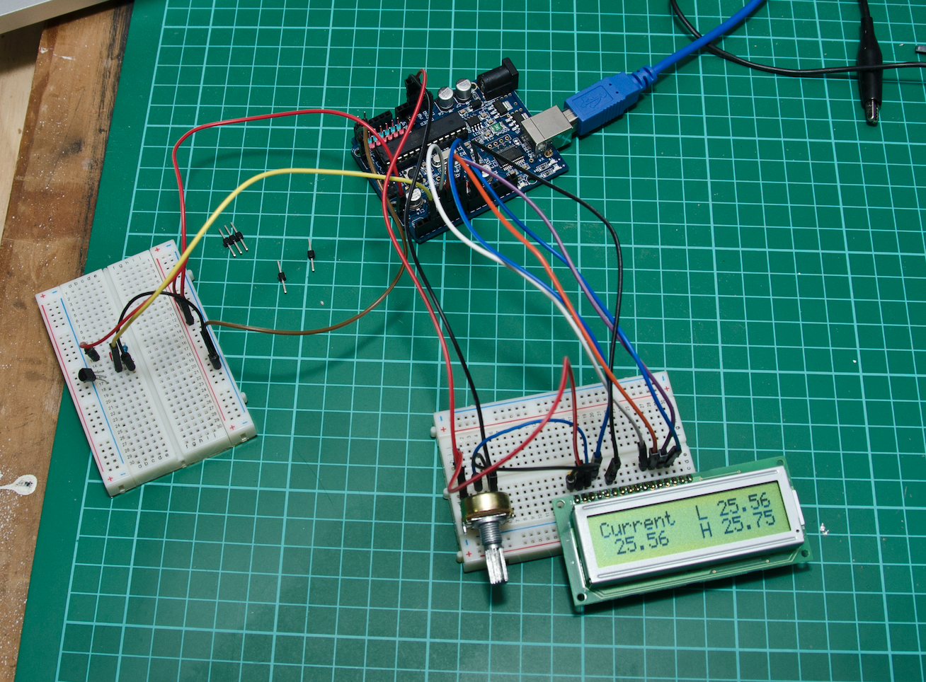
LCD wiring on the breadboard
lcd.print
lcd.print( ) is the command to send data to the lcd. The default settings mean the first character is placed at position 0 on line 0 (ie top left) and each subsequent lcd.print will advance one character along. The display contains internal ram and, after 40 characters, it spills over to the next line, filling this. To overcome this we need to manage the number of characters on each line. We can control their placement with lcd.setCursor (x,y) with x representing the character spot, and the y the line. Hence lcd.setCursor (0,0) is the first char on line 1, while (5,1) is the sixth char on line 2.
Scrolling
It is possible to scroll the display using the command lcd.scrollDisplayLeft() or commands, which steps the whole display one character. For this demonstration I have shown how to scroll just 7 characters on one line. The principle is that you select 7 characters from a larger message, and display them, then advance one place in the message, and select 7 characters, display…advance…display…etc. The result is a scrolling message that can be much larger than the space available, or the display.
This demonstration uses a pre-formed message, but it could be made up from errors message strings, or some other data that the sketch processes into a message. Some displays have a faster response (or greater persistence) than others, so some experimenting with the scroll speed may be needed to prevent “ghosting.” This seems to be more prevalent on the transparent displays (the pixel is clear rather than dark, ie white on blue background). Be aware that not all displays are created equal, and their performance can change with temperature. They are usually slower with low temperatures (the liquid in LCD causes this).
1: The l2c LCD wiring is considerably simpler 2: The pins assignments for the l2c LCD
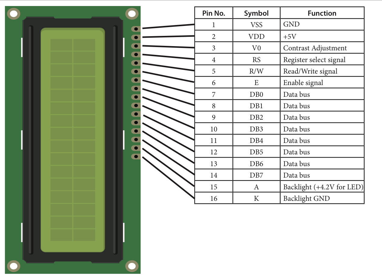
The pinouts for a typical 16×2 LCD
Backlights
LCDs work by reflecting light and either blocking or passing this light back to the user. Using an LCD with a backlight not only allows use in all situations, it provides a means to signal a user. You may want the display noticed when something changes, and goes out when acknowledged. You might turn off the backlight when a certain value is reached, or flash it.
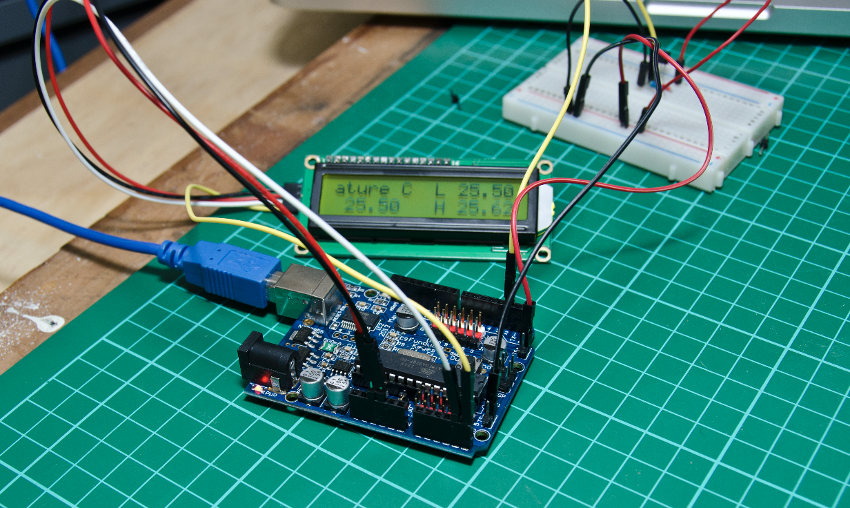
The temperature relay with an lc2 LCD
For the I2C display the command lcd.backlight() or lcd.nobacklight() controls it. For basic displays they are just a LED connected to a pin. This allows the brightness to be adjusted using PWM (for the I2C you can provide a separate connection). Some displays require the backlight LED to be connected to power. You can power it off the LCD power with the addition of a small 220Ω resistor.
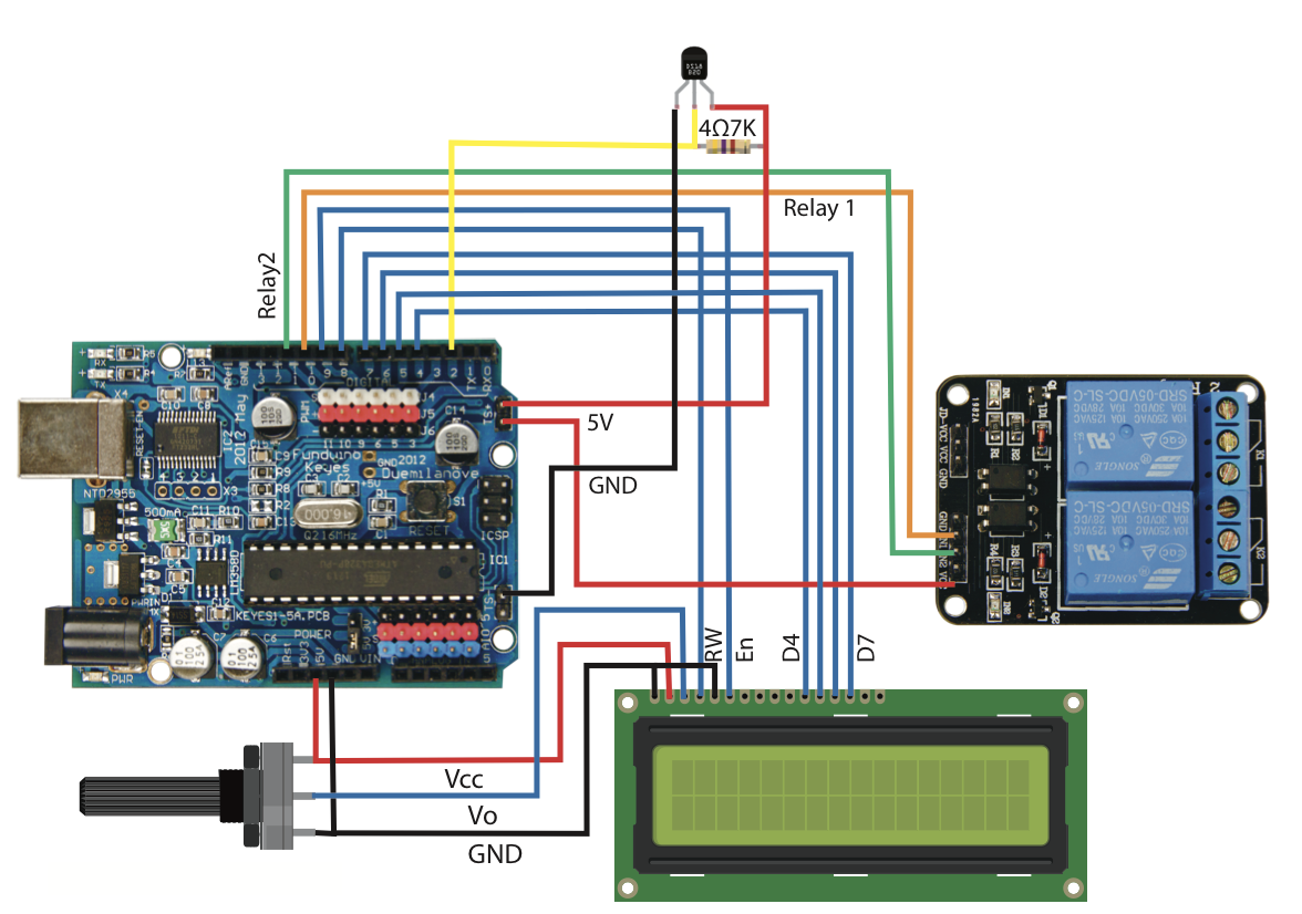
The wiring layout for the temperatrure relay with a basic LCD
Note: LCDs have an on-board processor that can get confused. A power reset is the only way to restore them. If in doubt, remove the power to the LCD and reset the Arduino before continuing. If you are unable to get any sort of response, check the contrast setting. Too far one way and you see nothing, too far the other and you just get blocks.
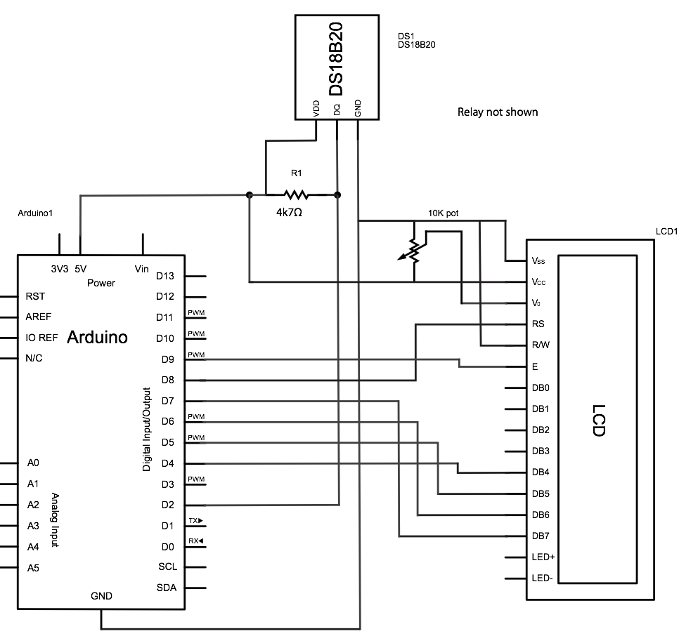
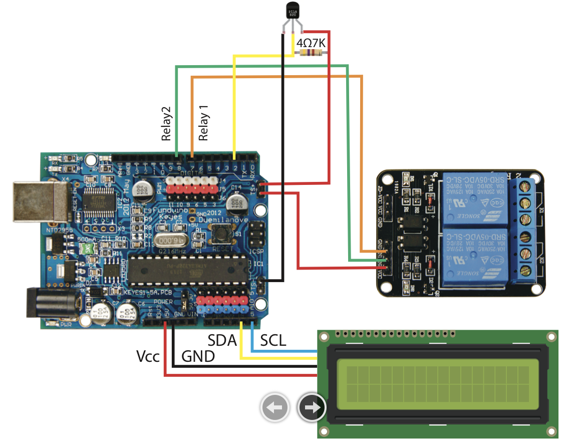
Wiring schematic for the temp relay
Sketch
The sketches add to the temperature regulator presented in the Dec 12/Jan 13 issue. We still control the relays, but display the current temperature, lowest and highest readings on an LCD. The sketch will still work if the LCD is not connected. (You need to restart the sketch if you add the LCD, so that the library can initialise it properly.)
There is more information on LCDs and arduino at both the www.Arduino.cc and www.adafruit.com. Fritzing is an Open Source design tool that allows you to design circuits and develop Printed circuit boards see www.fritzing.org
We have 16 x2 LCD modules available for sale on The Shed magazine website, www.theshedmag.co.nz.