Amplifiers are used in almost all electronic equipment. Here’s a basic guide to how they function.
By Barry Kent
Electronic amplifiers are widely used in almost all electronic equipment— they can either be a separate piece of equipment or an electrical circuit within another device. The ability to amplify is fundamental to modern electronics, where a small electrical signal is amplified into a larger output signal with increased power output or signal strength. Typical devices include the stereo amplifier, radio and television receivers, sensor devices such as strain gauges for measuring weight, light metering and environmental gas sensors. Amplifiers assist us in many ways throughout the day.
The amplifier is a high-gain device with one or two differential inputs and usually a single-ended output. Internally the amplifier consists of transistors and Field Effect Transistors (FETs) which amplify the input signal. Amplifiers can be categorised in different ways, either by the frequency of the electronic signal being amplified; such as audio amplifiers which amplify signals in the audio (sound) range of less than 20 kHz. RF amplifiers amplify frequencies in the radio frequency range between 20 kHz and 300 GHz. For measuring instrumentation equipment the quantity of voltage or current is amplified and displayed as a digital readout or displayed as a waveform on an oscilloscope. Amplifiers can be divided into voltage amplifiers, current amplifiers, transconductance amplifiers and transresistance amplifiers.
Bipolar Junction Transistor
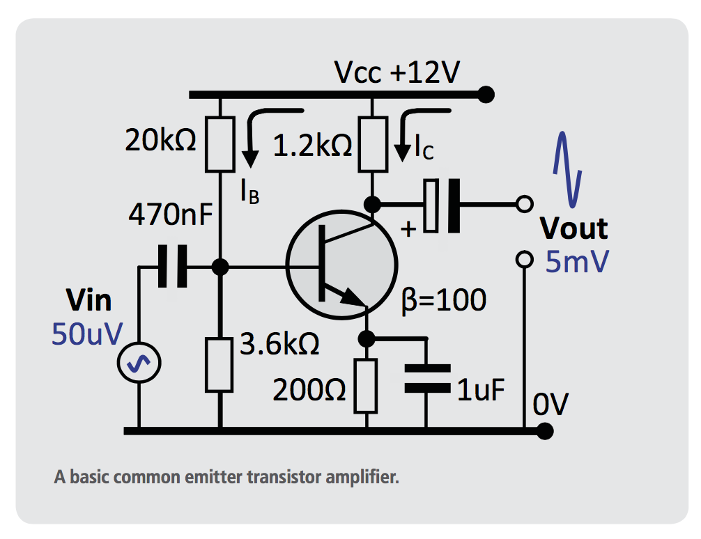
In the previous article about semiconductors we briefly examined the gain of a Bipolar Transistor circuit, where Gain (β) is the ratio of collector current I to base current I β = I / I . CBCB Transistor amplifiers operate using AC and DC signal inputs which must be biased halfway between the positive and negative supply rails (VBIAS = VSUPPLY /2). Circuitry is required at the front end of the amplifier to bias the inputs that will ensure the peak input voltages remain within the supply rails. The aim of any small signal amplifier is to amplify all of the input signal with the minimum amount of distortion possible to the output signal. In other words, the output signal must be an exact reproduction of the input signal but only bigger (amplified).
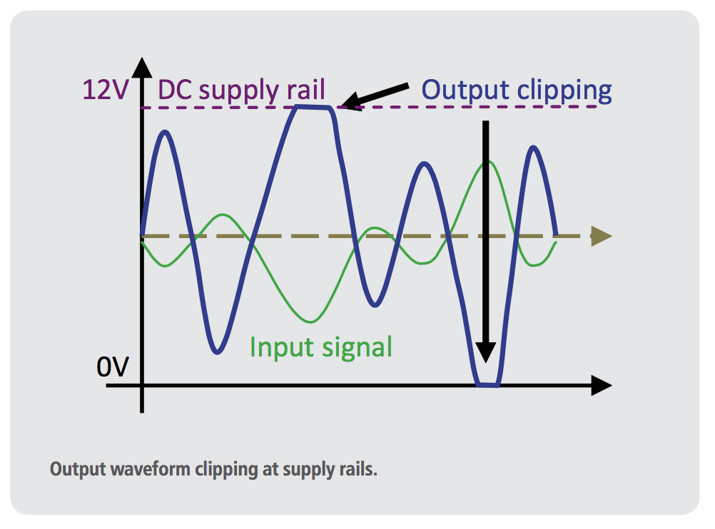
This transistor amplifier circuit has a 50uV ac signal superimposed onto the base bias current (IB), with a transistor gain β = 100 the output voltage signal will be 100 times greater in amplitude, therefore producing 5mV ac output signal superimposed onto the collector current (IC). The 470nF input decoupling capacitor ensures only the alternating input signal will be superimposed onto the transistor bias current, likewise the output decoupling capacitor will ensure an alternating voltage is produced at the output. The decoupling capacitors ensure external dc currents do not affect the amplifier circuit and bias levels. If incorrect decoupling capacitors are fitted the amplifier may go unstable, causing the output to go into saturation (full on) or switch off, causing distortion and clipping of the output waveform.
If an audio amplifier output begins to clip this will distort the sound quality, often heard as a harsh, distorted sound when the amplifier is set to maximum volume. Clipping may cause damage to the speaker if it doesn’t have sufficient protection.
MOSFET Amplifier
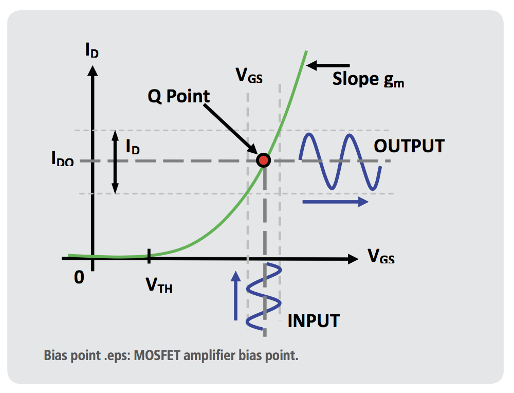
Enhancement MOSFETS (eMOSFET) conduct when a suitable gate-to- source positive voltage is applied. Due to the conduction characteristics of a MOSFET there is a minimum gate-to-source voltage called the threshold voltage (VTH) that must be applied to the gate before it starts to conduct allowing drain current (ID) to ow. In other words, a MOSFET does not conduct when the gate-source voltage (VGS) is less than the threshold voltage (VTH). As the gate’s forward bias increases the drain current (ID)— known as drain-source current (IDS)— will also increase, similar to a bipolar transistor, making the MOSFET ideal for use in amplifier circuits.
Unlike a BJT transistor, which is a current gain amplifier, the MOSFET conductive channel can be thought of as a variable resistor that is controlled by the voltage applied to the gate. This characteristic is called transconductive. The amount of drain current that flows through this n-channel MOSFET from drain to source (IDS) therefore depends on the gate-source voltage (VGS). The optimum point of operation is found by measuring the MOSFET conductive characteristics and plotting this onto a graph to illustrate the relationship (I- V) between the gate voltage (VGS) and drain source current (IDS).
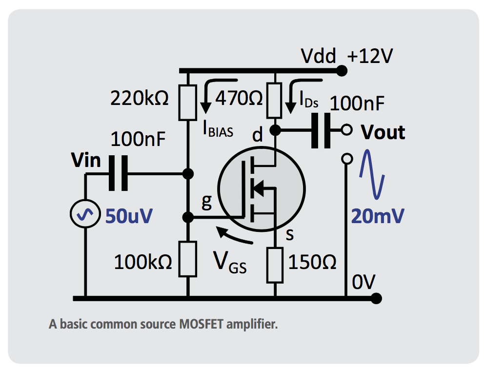
The input impedance of a MOSFET amplifier is much greater than the transistor amplifier, with little to no current required to drive the amplifier input. The circuit consumes less power and can provide a lower output impedance. The MOSFET amplifier has a high input impedance which is ideal for measuring very sensitive signal levels with a high impedance source. Many sensor devices produce a voltage signal but are unable to supply current. This MOSFET amplifier has a 50uVac input signal superimposed onto the gate bias voltage: Vg = 100kΩ/(100kΩ+220kΩ) x 12V = 3.75V ±50uV. The gate voltage controls a larger current owing from the 12V supply rail through the MOSFET drain to source terminals, resulting in an amplified voltage signal of 20mV at the MOSFET source pin. The effective gain β = 20mV/50uV = 400.
Operational Amplifiers (Op-Amps)
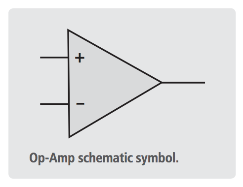
The operational amplifier, often called Op-Amp, is a high-gain electronic voltage amplifier. It has two differential inputs and usually a single-ended output. Internally the Op-Amp is a miniature circuit consisting of FETs, transistors, resistors and diodes that provide the bias networks, overload protection and stability for the Op-Amp to operate effectively with minimal external components.
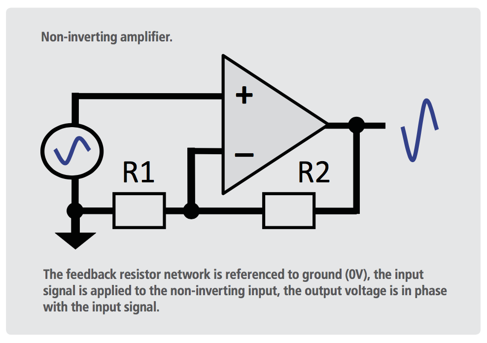
In this configuration the Op-Amp produces an output potential relative to circuit ground that is typically hundreds of thousands of times larger than the potential difference between its input terminals. The amplifier circuit is configured with feedback resistors R1 and R2 so whatever input voltage is applied between the non-inverting input (+) and inverting input (-), the output will swing towards either supply rail to keep the two inputs at the same voltage potential. The output will swing towards the positive rail whenever the non-inverting input is slightly higher than that applied to the inverting input. Likewise the output will swing towards the negative rail whenever the non-inverting input has a slightly lower voltage than that applied to the inverting input. With no feedback resistor network the amplifier gain is considered in nite. Most amplifier spec sheets will list the maximum open-loop gain. The feedback resistor network sets the gain β of the amplifier circuit which is calculated β = (R1 + R2)/R1.
For example R1 = 10kΩ, R2=90kΩ, the calculated gain β = (10k + 90k)/10k = 100k/10k = 10. With a 250mV input signal the output is calculated 250mV x 10 = 2.5V. With R1 not fitted and R2 set to a low value or 0Ω resistance, the amplifier is operating at unity gain. A unity gain amplifier provides a low impedance output signal for a high impedance input voltage signal that is unable to deliver a current source.
Motor Current Sense Amplifier
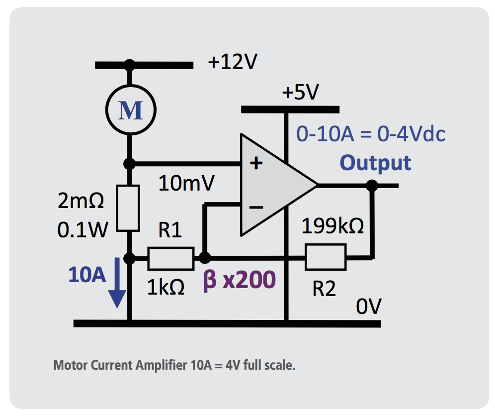
Amplifiers are commonly used in motor load current monitoring systems, where a small voltage drop across a current sense resistor is amplified to provide an output signal suitable for measuring with a microcontroller analogue input.
In this example the motor current measures 2 Amps at full load, however during overload situations the motor current may peak up to 10 Amps (x5). The current sense resistor in series with the motor is selected to produce a small voltage drop that is in proportion with the motor current. The value of the current sense resistor is kept very low to avoid excessive power loss— using ohms law we can calculate the power rating of the current sense resistor: I2 x R = P (watts).
For example, the power rating of a 0.1 ohm current sense resistor is calculated 10A2 x 0.1Ω = 10 Watts, which is a large resistor that will get very hot and will cause unnecessary power loss. The following example uses a 2 milliohm (2mΩ) current sense resistor that will dissipate just 200mW with a 10A load current. The voltage across the sense resistor is measured as (I x R = V), 10A x 2mΩ = 20mV. The microcontroller analogue input range is 4V, therefore the required amplifier gain is calculated (β = Vout / Vin), β = 4V/20mV = 200.
The gain of the amplifier circuit is set by the feedback resistor network R1 and R2, calculated gain β = (R1 + R2)/R1 = (199kΩ + 1kΩ) / 1kΩ = 200.
The Audio Amplifier
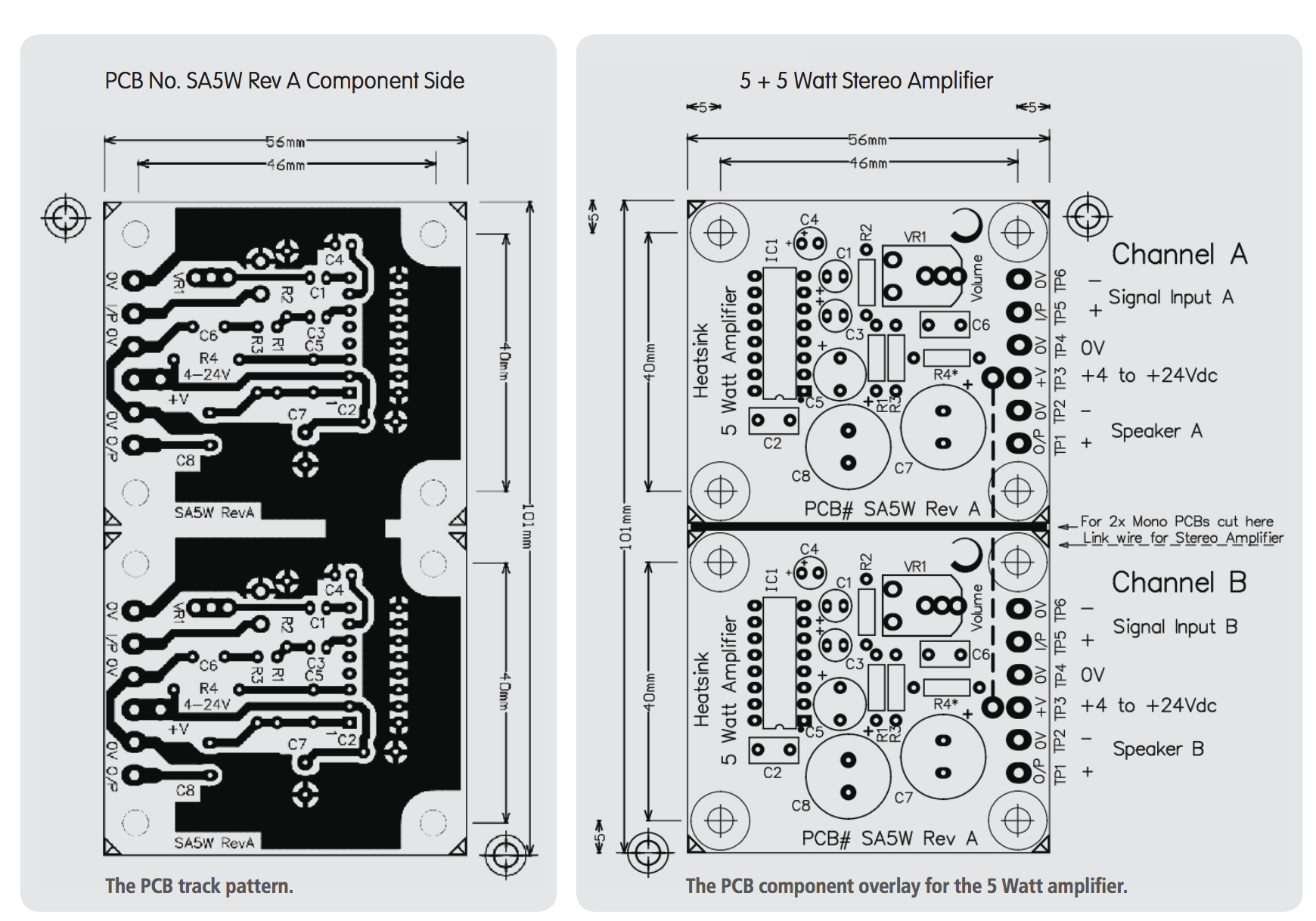
The following 5 Watt Audio amplifier is a typical example where the TDA1905 amplifier IC is designed to reduce the number of external components on the circuit board. This circuit will use a 12Vdc supply, although the amplifier IC can operate up to 30Vdc max. The amplifier can receive an audio signal supplied from an iPod or similar device to drive the 5 Watt speaker.
An adjustable trimpot resistor VR1 is set to attenuate the input signal to a suitable level to keep the volume within a suitable range and stop the output clipping while the iPod is set to maximum volume. Decoupling capacitor C1 and C3 eliminates DC current entering the inputs, resistors R1 (10kΩ) and R2 (100Ω) provide a gain of 101, β = (10k+100)/100 = 101. Resistor R3 (1Ω) and capacitor C6 (220nF) provide damping of high-frequency resonance that may occur between the amplifier output decoupling capacitor and speaker coil inductance.
This amplifier operates with a single supply rail where the output resides typically halfway between the supply rails when no signal is present at the input. If the speaker is connected directly across the output and ground rails then dc current would constantly ow from the amplifier output through the speaker coil to ground (0V), which would cause damage to the speaker and thermal overload in the Op-Amp. Therefore capacitor C7 (1000uF) is fitted to decouple the amplifier output providing an alternating current to the speaker with no dc current component.
Capacitor C5 provides the bootstrap supply for the top portion of the amplifier driver circuit—this enables the output to pull up to the positive supply rail. Capacitor C4 assists the amplifier to reject ripple voltage on the supply rail. The 1000uF supply capacitor C8 provides a low-impedance supply to reduce ripple voltage on the supply rail and ensures the amplifier operation is stable, which is essential for good-quality sound reproduction. Capacitor C2 is essential to filter out high-frequency currents that may appear from amplifying high- frequency signals. Without these capacitors fitted the amplifier could become unstable, creating high-frequency tones and distortion. Frequencies could be generated above human hearing range where the amplifier will draw high-frequency currents, resulting in excessive loading where the amplifier could exceed its temperature rating and thermally shutdown.
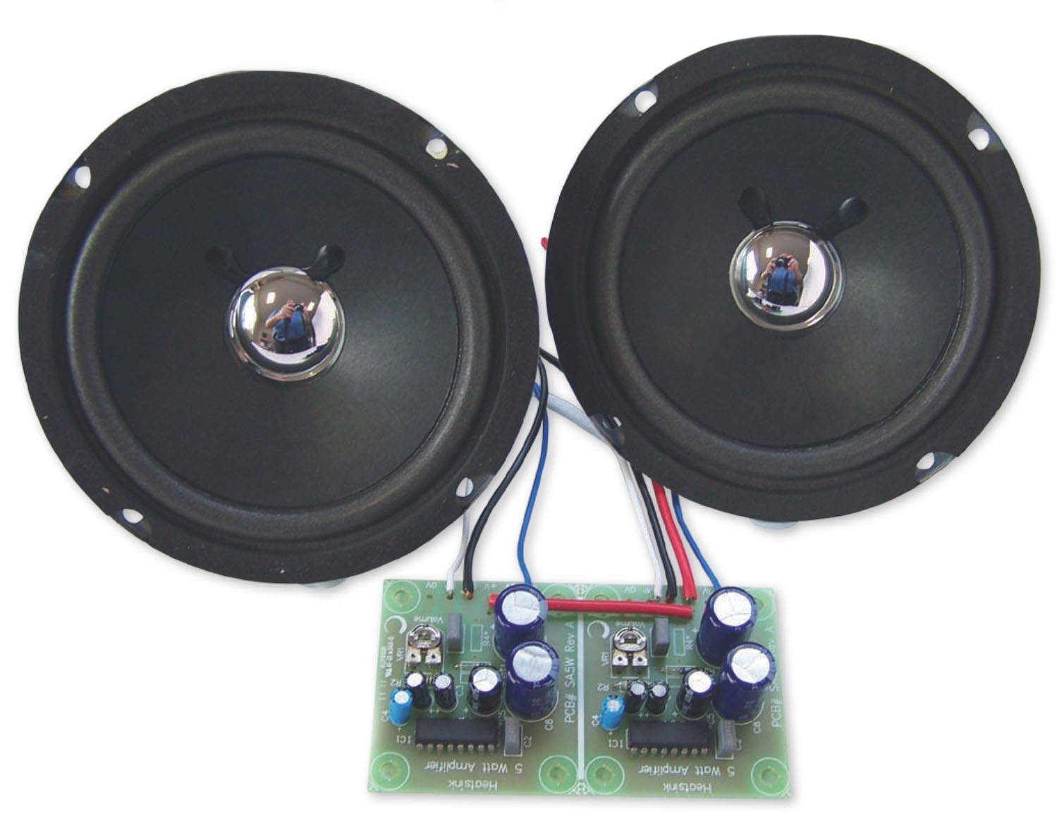
Amplifier Kit
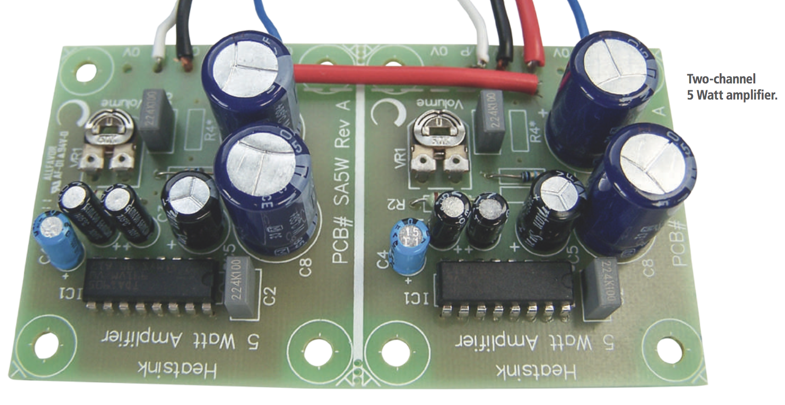
This amplifier kit uses two mono- amplifier circuits placed in duplicate on one Printed Circuit Board (PCB) to provide a Stereo 5+5 Watt amplifier. The SA5W PCB may also be cut down the middle to create two individual mono 5 Watt amplifiers. The amplifier circuit consists of a TDA1905 monolithic integrated circuit in a 16pin Power-Dip package, intended as a power amplifier for a wide range of applications including radio and iPod amplifiers, etc.
This amplifier kit drives two 125 mm 6W 4Ω speakers. A panel-mount DC power socket enables the user to connect a 12Vdc 1A power adaptor. The 3.5 mm panel-mount stereo socket enables the user to connect a 3.5 mm stereo cable lead between the amplifier and remote sound- recording device. Sound quality is very clear with the combined 10 Watts at maximum volume.

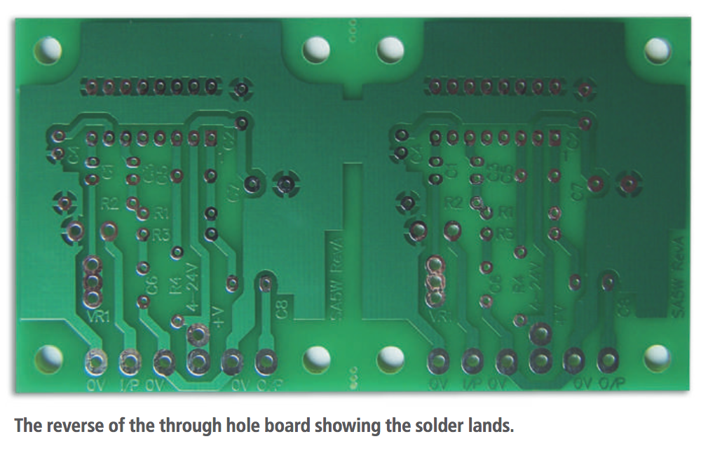
The pins on the far side of the amplifier chip function as a heatsink to dissipate heat. The large copper trace area helps to conduct this heat away from the amplifier IC, therefore the circuit board needs to have free air ow to avoid the amplifier going into thermal shutdown while operating at maximum volume.
The PCB boards and other components are available in bulk for schools from Barry Kent through his website http://www.qsm.co.nz