Build one of the most-used tools in the workshop
By Geoff Merryweather
A linisher is near the top of the list of the most-used tools in the workshop, whether for deburring steel to stop cuts in the hands, or sharpening tools and drills. There are few projects where it doesn’t get used. They seem to be expensive for what they are, and can easily be made for a fraction of the purchase price. The budget using new parts for this project is around $400.
My first linisher cost $101 in the mid 1980s when I was still at school. The front wheel cost $99 from Charles Palmer Ltd in Hobson St, next to Shroff and Sons. The other $2 was spent on a flat-belt pulley and a washing machine motor. A linisher is essentially two or more wheels in line with an abrasive belt and powered by a motor and with some means of tracking and tensioning. There are many variations—knife- makers and woodworkers have their own specific requirements— and an advantage of making your own is it will suit your needs.
The front wheel needs to be rubber-coated or the abrasive particles will be shredded from the belt. The softer wheel, combined with the diagonal grooves, makes it work faster. Skateboard wheels are on some homemade machines, but the real thing works better. There is a platen for flat surfaces and a section without the platen for the outside of pipes and similar work.
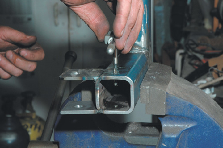
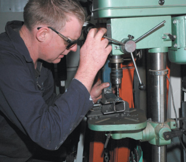
1: Tapping bolt holes 2: Drilling arm
Design
I use the front contact wheel for more than 95 percent of my work. The tracking is adjusted so the edge of the belt is clear of the wheel for cutting into corners and tight spaces. No spindles or bearings should get in the way and one side of the linisher should be clear of obstructions. To work areas like knife handles between the guard and the rear pommel, a narrow front view is needed without a spindle in the way.
My design needs to be flexible so that with little modification I can swap my 75 mm and 250 mm front wheels quickly. Space is always at premium in the workshop, so con- sider the footprint.
All this drives the design. To be compact, the arm coming out with the wheel should have integral bearings and fixing that does not protrude. So I put the tracking and tension on the third wheel at the rear of the machine.
The 1520 mm belt is a common size that does not take up too much space. A longer belt makes the ma- chine easier to build as there is more space for the tensioner and tracking mechanism. I can replace the front arm with a longer one if I come across longer belts at the right price.
The motor and drive-wheel speed give the belt speed. You want around a 150 mm wheel with a 2800 rpm motor or a 300 mm wheel with a 1400 rpm motor. My belt size and drive wheel led to a 2800 rpm motor. A 2440 mm belt would make a 300 mm wheel and the associated tensioner arm feasible and the 1400 rpm motor is much easier to find and cheaper.
Materials
The machine is built from mainly 40 mm and 50 mm RHS. My front contact wheel came from my first sander but they are available as spare parts from suppliers such as Chevpac Machinery. This is usually the most expensive part of the exercise.
The motor in my case was a new 1.5Kw motor, costing $160 from TradeMe. Second-hand 2800 rpm motors are not common. An alternative is a bench grinder. It is easier to fabricate a drive wheel for this as there is no requirement for a hub. Machinery House had an advert in the last issue of The Shed for a 200 mm 1hP grinder which would be suitable for this project. The small- er grinders are generally limited to a 1/3 – 1⁄2 hp motor power.
Drive wheel
I fabricated the outer rim of the drive wheel from 135 mm pipe (since I had some) with a dough- nut of 8 mm plate and the hub 50 mm. The drive wheel and tension- er wheel are both wider than the belt to allow for misalignment and space for sideways movement.
Cut out the doughnut to be a snug drop-in fit into the middle of the pipe. Clamp it down so that the end of the pipe and the plate are flush and weld it into place. Put the whole assembly into the lathe and bore out the centre to take the centre boss. Bore out the centre boss to around the 3/4 finished bore size and drill and tap for the retaining screw to hold it onto the motor shaft. If you forget to do this as you are truing (to get it finished before the kids go to bed and it is noise-curfew time) and weld it before it is assembled, the neighbourhood may discover some new words. You will also have to make an extended tap and drill through the outer rim afterwards; it won’t be quite as balanced.
Clamp the centre boss into place and weld it in. The whole lot then goes back into the lathe for final finishing. You want to true up the outside, back and finish-bore the centre in a single setting so it will run true. If you don’t have a lathe to make a metal drive pulley, you can laminate MDF and screw it onto a V-belt pulley for the hub, or use a grinder as the motor and mount the wheel like a grinding wheel.
Axles
The axle dimensions depend on your front contact and tensioner wheels and bearings, so you will need these first. The axles are turned out of 20 mm round bar. The wheel is retained by a capscrew and washer which threads into an axial hole drilled in the outboard end. For clearance, this makes the smallest projection on the side. The axle length from shoulder to end is the wheel width less 0.5 mm or so My small front wheel has a 1⁄2-inch axle, so I used a 6 mm capscrew and washer. The tensioner wheel uses a 17mm axle, so uses an 8mm capscrew. Aim to have a washer just big enough to pull against the inner race.
The other end is turned to 12 mm, leaving a shoulder which provides the spacing for wheel alignment. This lets you clamp the axle square against the mounting arm for welding.
Frame
The linisher frame is an L-shape, made from 65x50x5mm RHS. The face parallel with the belt is used for measuring the location of the parts so the wells are in line. When the belt is running central on the wheel it will be flush with its face.
The front arm that takes the front contact wheel is 40x40x4mm RHS. Grind back the corners of the RHS and it will slide into the frame with no slop. If the weld bead in- side the 50 mm RHS is too large, either flatten it with a die grinder or use some careful taps on the face of the 40mm RHS to form a hollow so it will slide into place.
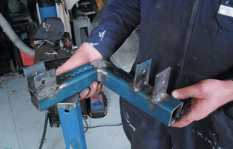
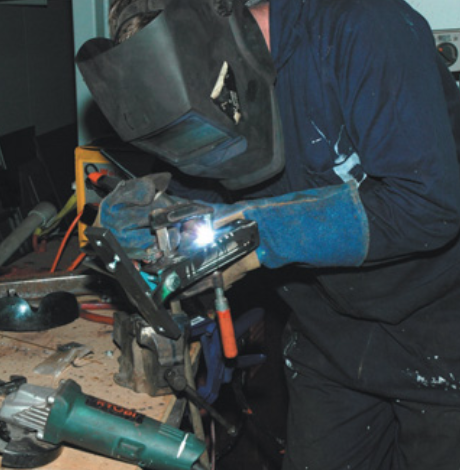
1: L-shaped linisher frame 2: TIG welding stud
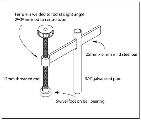
Stand
Next make the stand, as you need to start hanging pieces off the frame and measuring for alignment. The stand has a cross-shape base with a 50x50mm RHS upright and a cross 12 mm hole, 25 mm down from the top. Next time I would make the base with three feet in- stead of four so it sits level on an uneven floor.
To locate the frame on the mount so that the centre of gravity was in line, I assembled the drive wheel and motor and placed it on an angle so that it balanced on the edge. Measure from the face of the wheel to the balance point and allow for half of the additional width of the drive wheel over 50 mm i.e. if you measure 180 mm, and the wheel is 70 mm wide (that is, 20 mm over the 50 mm), then the distance to the centreline of the stand will be 10 mm less, 170 mm. From 50x5mm flatbar, cut the tabs that connect the frame 50 mm long. At 20 mm from one end, drill a 12 mm hole. Weld the first tab at a 25 mm offset from the number you measured above (145 mm to the face fixed to the stand, in this example), assemble and bolt up the second tab and weld it into place. This allows you to rotate the machine to suit access and working height.
Clamping front wheel
Front arm
The front arm is a piece o f40x40mm RHS with a 40x10mm bar to take the axle and front wheel. Since the centreline of the wheel needs to be in line with the centreline of the RHS, the bar is offset with a 10 mm spacer and the 5 mm shoulder of the axle brings everything into line again. You may want to wait until this stage to turn the axle so you can assemble the front arm into the frame, clamp a straightedge to the side of the frame and measure everything up directly. Round off the sharp corners, especially by the contact wheel so if the belt runs off the side it won’t tear.
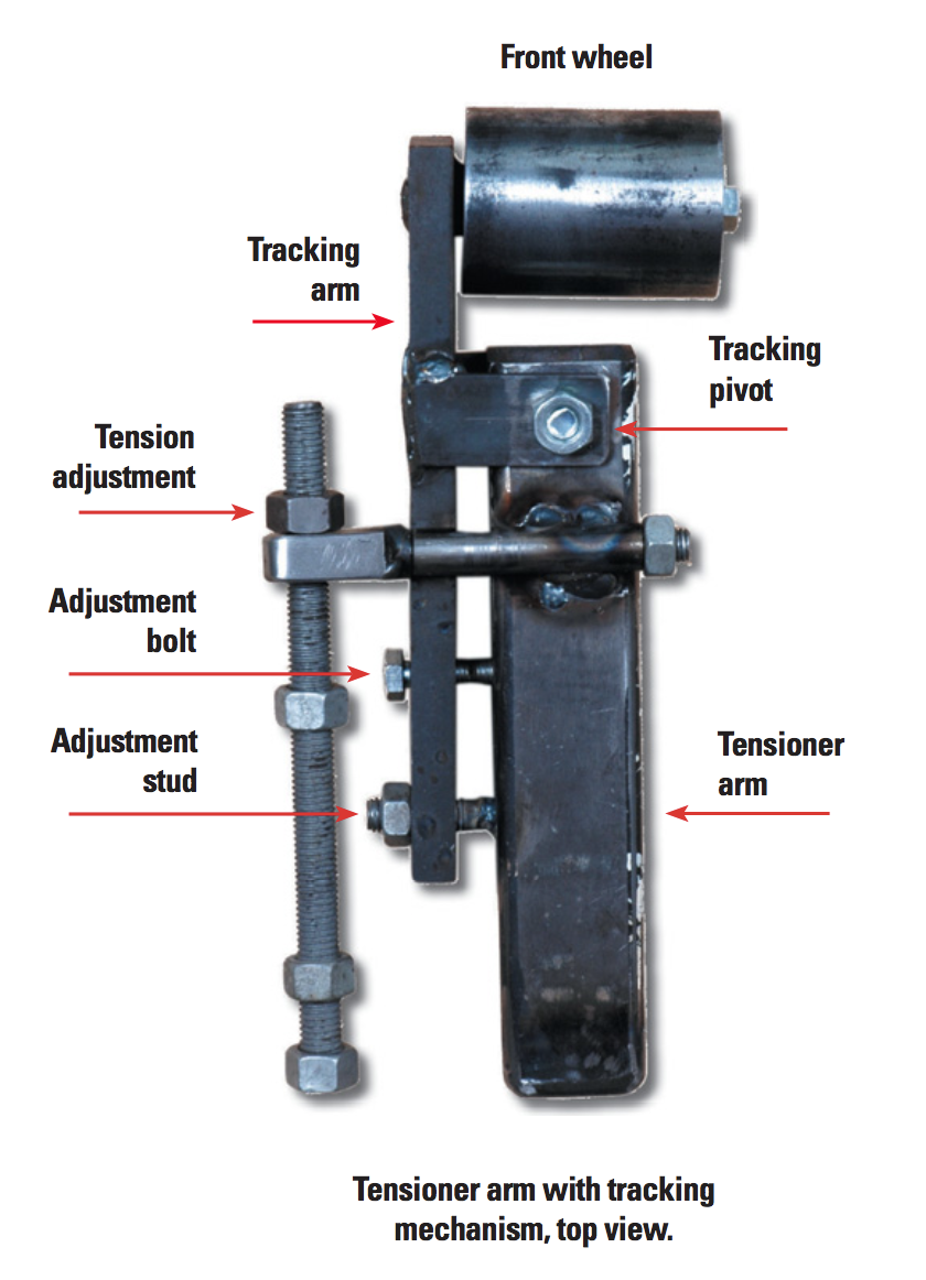
Tensioner arm
The tensioner arm pivots to provide tension to the belt, with another tracking plate beside to allow the tensioner wheel to move laterally so the belt will track left or right. The tensioner arm is 40x40x4mm RHS, hinged from two 65x50x5mm tabs like those holding the frame to the stand. As the overall width should be 50 mm, weld on one tab flush with the face of the frame, bolt up the assembly and weld on the other tab.
Clamp the motor onto the frame and fit the front arm and belt and check the space available.
Drill the 12 mm cross-hole to form the tracking mechanism hinge at the opposite end, and opposite faces of the tensioning pivot.
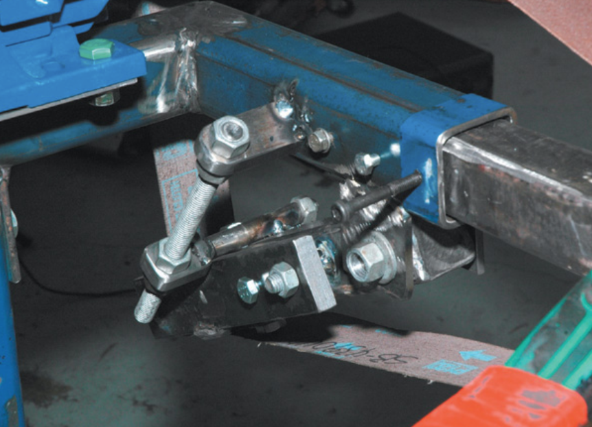
Tensioner tacked. Tensioner arm tacked
Tensioner
The tensioner itself is a piece of 12 mm threaded rod acting on two tabs. One tab is welded to a 10 mm bolt which fits through a piece of 3/8” tubing to allow it to pivot as the arm moves. You will need to run a 10 mm drill through the tubing to allow the bolt to fit. The other end is welded to the frame, although making this a pivot will give you more movement in the tensioner. Fitting this is the last step so make the bits and put them to one side.
Tracking mechanism
The tracking mechanism, a small 210 mm-long plate parallel to the tensioner arm, pivots on the tensioner arm to force the belt to one side or the other. The pivot is located on the tensioner arm centreline (and the centreline of the belt and main frame). There are two bolts to adjust the tracking. One is threaded into the tracking plate and tensioner arm and turns to push the plate away from the tensioner arm. The other close by is a stud in the tensioner arm and though the tracking plate. A nut on this stud turns to pull the tracking plate closer. They work to move the belt left or right. Again, round off all the sharp corners to protect the belt.
Bolt the 32 x 65 mm tabs onto the tensioner arm and clamp in the tracking arm or plate and tack weld. Mark up and drill the holes for the axle and the two track- ing bolt holes. One hole is tapped. The other for the 10 mm stud on the tensioner arm is 13 mm so it is oversized to allow for movement for the tracking arm. Bolt up the completed tracking arm onto the tensioner arm and use the oversized hole as a guide for the position on the tensioner arm. Don’t drill all the way through—you just want to mark the position on the arm for the hole to take the stud. Drill the hole in the tracking arm for the 10 mm stud and weld it in place.
Fitting axles
The axles are turned with a 12 mm stub, the same length as the thickness of the arm they are going into and with a heavy chamfer to give good weld penetration. Drill a 12 mm hole in the arm to take the axle and push into place and clamp so the shoulder is hard against the arm.
The clamp will generally limit your access to the out- side, so I welded around the shoulder of the axle to the arm with the TIG. If it is a good press-fit into place and doesn’t need a clamp, you don’t need this step and can just weld around the outside face of the arm.
Assembly
Clamp the motor and its mounting plate into position, and use a straightedge to check the alignment between all the wells and measure off the face of the frame to make sure everything is parallel. The drive and tensioner wheels are wider than the belt to allow for some misalignment and for the belt to move sideways when tracked clear of the edge of the contact wheel. Tack the motor mounting plate into position and check everything is OK. Fit the belt to the machine and look at the edges of the belt against the wheels as an alignment check. Note that sanding belts have a direction arrow in the inside. If you run it backwards the splice will peel apart.
Around this time, you will have an overpowering urge to turn the machine on and see it run. You can try it out, but without the tensioner fitted the belt tracking may not be great. Hold the tensioner arm down to tension the belt and give the drive pulley a flick by hand to see if it is tracking true. Adjust the tracking to move the belt in or out until it is running on the centre of the front wheel. Give the motor a one-second burst and see if the belt stays running true. As long as it stays on the wheels you can walk it in or out with the tracking mechanism. Next step is to fit the tensioner itself. Push the arm down to tension the belt, clamp the tensioner pieces in place and tack them on. Do up the tensioner nuts and start the machine up. If it runs well without slipping, then finish welding everything up and try it out.
Platen
The platen is used for flattening surfaces. It is a piece of 50x50mm angle with a 40×40 mm RHS offcut. The ends of the platen must be well rounded so the belt isn’t damaged as it rides up onto it. The top of the platen should be slightly higher—say 2 mm or so— above the line from the drive wheel to the contact wheel. I simply fitted and tensioned the belt and clamped everything in position, tacked it, checked it and welded into place. Make sure the edge of the platen is parallel with the reference edge of the frame. Mine is shorter than most as I have a 250 mm contact wheel as an alternative front wheel, which limits the length. If you just have the smaller size, make the platen longer. Make sure to leave a gap of say at least 150 mm between the platen and the contact wheel as a slack belt area for rounding corners, pipe, etc.
Contact wheels
One of the items on the design list was to be able to use different-sized contact wheels easily. The front arm has a collar made from 50×50 mm RHS so that it can be removed and replaced easily. This allows you to make another front arm to suit a different-sized wheel and change between them. The main thing to remember is the tangent at the top of the wheel is the same for each wheel, so the platen will work for all wheel sizes without alterations. The easiest way to set them up is to fit a belt, and clamp an angle to the platen, so you can clamp the wheel to the angle and measure the axle position to suit.