By Tony Cullen of Cullen Equipment Specialist
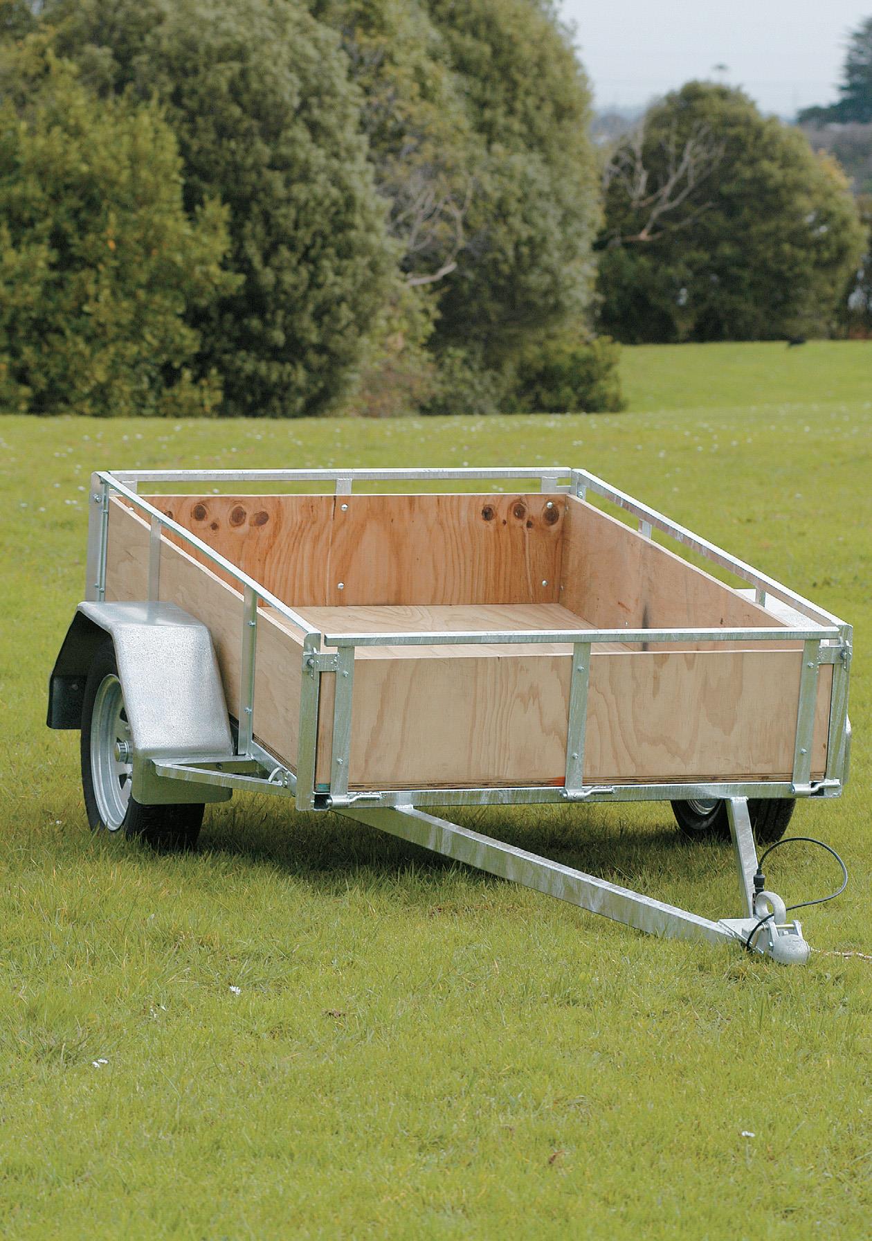
When you need to move some garden rubbish, shift furniture for your children’s flat, help a mate carry some gear or bring home some new purchase on the weekend, it’s very handy to be able to grab your own trailer from the backyard.
Components List
1 galvanized tow coupling
4 high-tensile steel zinc-coated coupling bolts 1 2000kg- rated high-tensile steel safety chain and shackle
Hub and stub set
2 x 330mm rim wheels
Springs kit: 1000kg multi-leaf springs, spring, slippers, spring hangers, bolts and nuts
4 U bolts, 2 galvanized U-bolt plates
6 tail gate hinges, 6 hinge pins
4 bolt-on antiluce tailgate toggles
2 toggle eye plates
2 tail-light assemblies
2 galvanized mudguards
Plug and plug holder
WOF holder
* Trailer components supplied by Trailer Components, Hamilton.
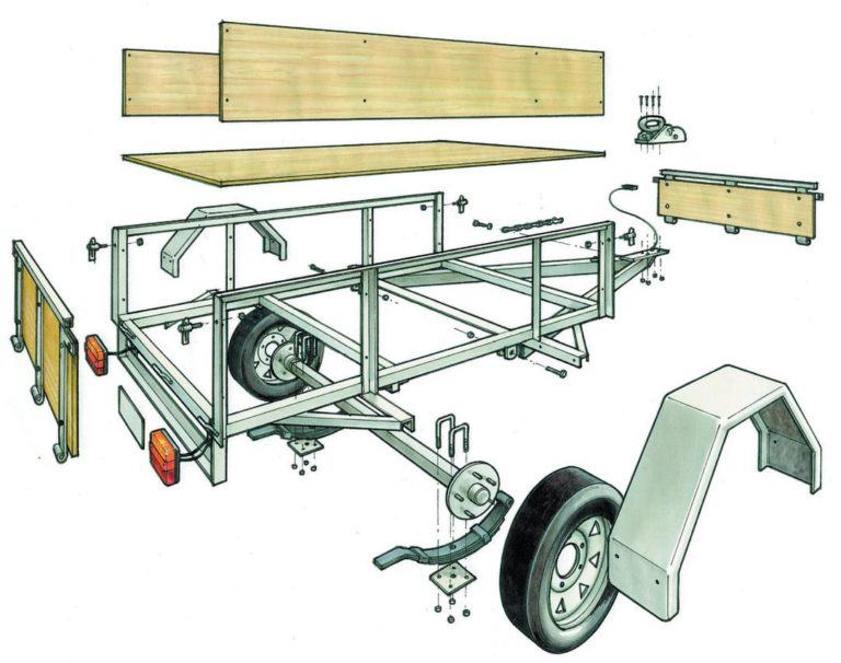
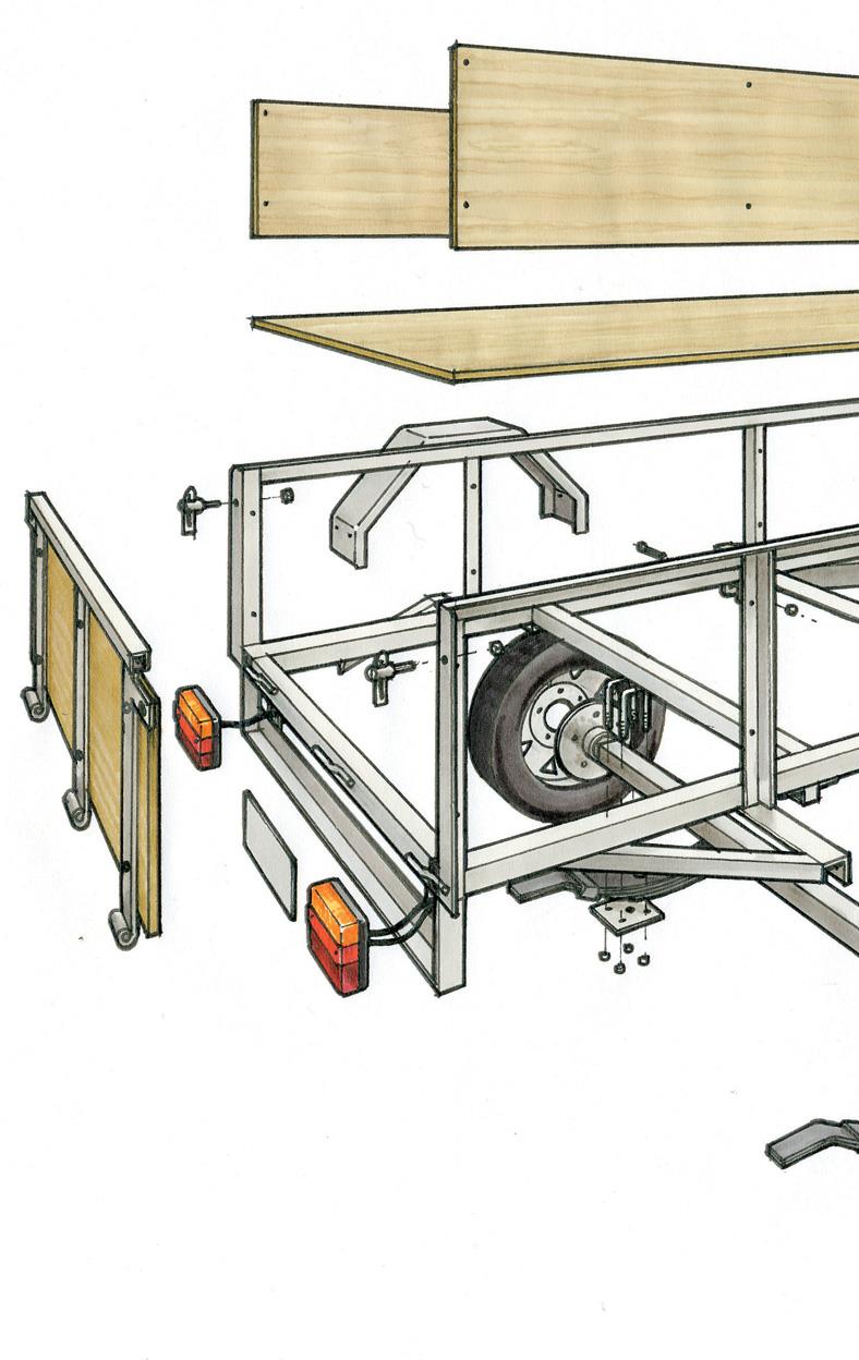
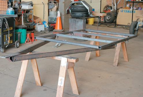
WITH MINOR VARIATIONS, I have built a standard 1200mm x 1800mm (or 6ft by 4ft in the old measurement) domestic trailer with a solid frame of box section or rectangular hollow section (RHS) mild steel. The frame is braced by angle-iron cross members and has a sturdy, ply wooden deck. It’s best to use not less than 5-ply 12mm minimum – in this case we have used 7-ply 17mm. The tailgate and the front gate have the hinge pins all facing the same way, so the gates can be taken off when you want to open up the trailer for carting over-length timber.
Welding is the key to putting together the frame, and a cutting list of the lengths of steel is provided. Steel RHS comes in eight-metre lengths, angle iron in six-metre lengths so it will need to be cut to size. The principal trailer components – coupling, safety chain, mudguards, wheels and so on, as outlined in the components list – can all be bought from regular suppliers. Full assembly instructions come with the components.
1
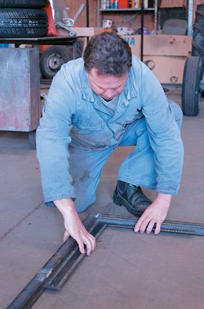
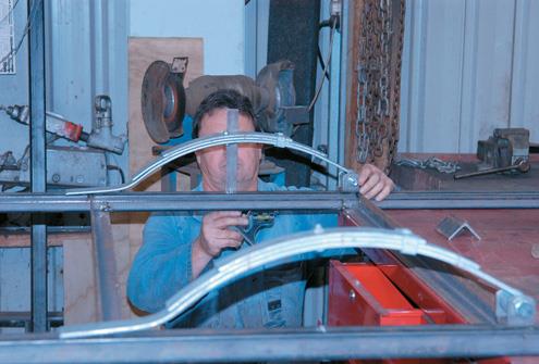
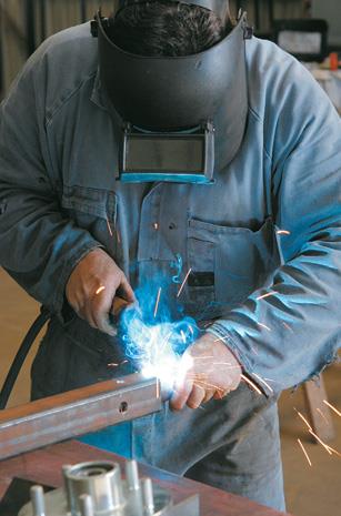
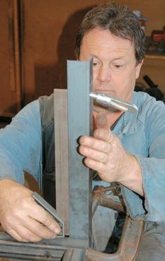
A crucial step in building the trailer is to get the axle stub straight, otherwise your tyres will chop up as they run. I use a jig of angle iron to get this straight. But I can show how to do it for home workshop, simply by holding the axle stub firmly against the bottom and one side of the box section axle to ensure it is square. There must be good welds on the axle stub.
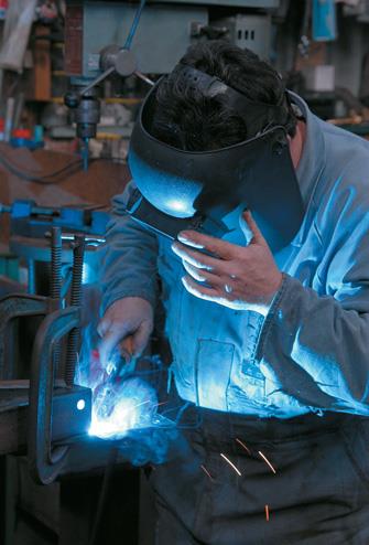
The plate where the coupling is bolted must be strongly welded to the drawbar for safety reasons when towing. If you have any doubt about your welding experience, have an expert do the coupling plate weld.
Clamps are a very important part of building the whole trailer – they are used every step of the way. It will speed up the assembly of the trailer if you pre-cut all material. I then mark all the pieces, especially with top, bottom and sides, and front and back.
2
3
4
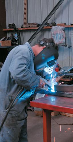
While home workshop owners are exempted from having a New Zealand Standard (NZS) 4711 welding certificate when making a domestic trailer, the welding is required to be up to the joint Australian New Zealand AS / NZS 1554 (in part originally NZS 4701). For a Warrant of Fitness, the welding is checked thoroughly visually on a new trailer.
Frame lay up
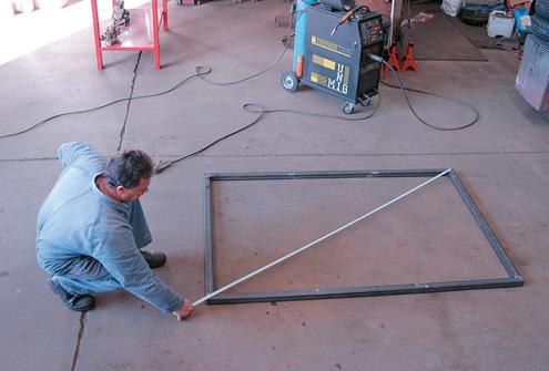
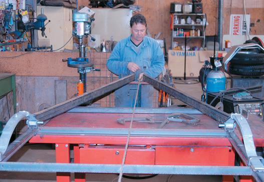
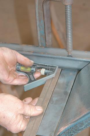
Chalk a straight line on the ground or bench, and lay up the side and back of the frame. The outside cut of the RHS may not be straight, so check with a square on the inside measurement. The first right-angle between the side and back is important as other measurements all depend on this first corner. (1) Tack weld the first corner on its own.
When all four RHS sides are laid out, tack weld. I have made the trailer an extra 10mm wide
(1210mm = 1130mm cross-frame angle iron + 2 x 40mm width of RHS sides). This is in case the plywood sheet is not exactly square — it allows room to make it easier to drop in. Check both diagonals of the frame are equal to ensure it is square. (2) It is harder to do on the floor because you can’t clamp it, as on the bench.
5
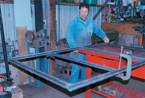
I prefer to work with the frame on a bench. I clamp the tack-welded section to the bench and tap it with a hammer to get the tack weld straight (checking all the time with the square). At this stage you are working with the frame upside down. It is easier to place the heavy drawbar resting on the frame, than to hold the lengths up under the frame. While the trailer is upside down, I do the frame and drawbar, springs, axle, hubs and wheels. Then I turn it over to do the mudguards, mounts for the side bars, front and tailgate and lights.
Angle iron cross members
Drill a hole on one side of the angle irons near the end for the lights cable to go through. Tack weld the two cross members at equal distance from the ends of box section the trailer frame and from each other. I set the angle iron cross members at 600mm. Clamp small pieces of metal under the frame as it sits, and rest the angle iron on them. (3) Tack weld cross members. (4) You could use for cross members, but angle iron is cheaper and does the job. Keep the angle iron flat in line with what will become the top of the RHS frame, as the wooden deck will be screwed to the angle iron cross members.
6
Springs
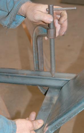
The springs for this trailer have a 1000kg weight loading. People have to be aware of the weight limit when loading up the trailer with things like builder’s mix. Set the springs, with their centre pole for the axle over the 900mm centre of the 1800mm side frames. Centre the axle so the 40kg weight of the drawbar is a bit forward, otherwise the trailer would rattle when travelling empty. You need to know where the springs are placed first, in order to locate exactly where the drawbar sits back on the side beam. Check that the springs are square. (5)
Now place the bolt frame and slippers for the springs. Allow 50mm of spring to come through at the back of the slipper. (6) I have seen the result if there is no allowance, and the spring compresses suddenly, say, if you bump over the gutter when reversing. The spring pops out of the lens of the slipper. Then you have to unbolt it to put it back. Tack weld both the front attachment to the beam where the springs are bolted into place and the slipper at the back.
7
8 & 9
10
Drawbar
The A-shape of the drawbar is stronger than a single, straight steel drawbar. If you jack-knife the trailer, you can hit the side of an A-frame drawbar and kink it a little, but it is stronger than the straight drawbar.
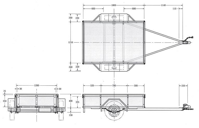
The drawbar can be as long as you want, but the rule of thumb is not to get it too short, because then it is too hard to reverse the trailer. The minimum length for the drawbar should be between 1200mm and 1500mm from the front cross member to the tow coupling. I have decided on a drawbar of RHS beams 1800mm long overall.
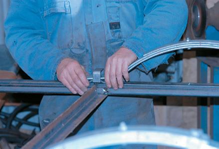
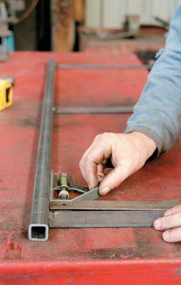
Place the drawbar back towards the springs, so you can have welds on both the front beam and side beams. To get the drawbar centred, mark the 605mm centre point in the 1210mm width at both ends. Take a string from the back frame and across the centres to the tip of the drawbar to get the drawbar central. (7) Butt the drawbar together on the centre mark.
The drawbar sides should be flush with the side beams where it is to be welded.
The length of the drawbar should now be 1140mm from the drawbar tip to the front beam. By the time the coupling plate is welded on the drawbar, the total length will be around 1300mm. Tack weld the back of drawbar to the beams. (8)
11
Coupling plate
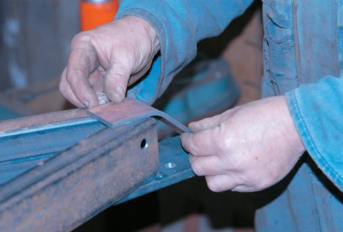
Drill holes in the coupling plate, using the bolts placed through the coupling for marks. Clamp the coupling plate to the drawbar underneath, leaving the bolt holes clear. (The coupling plate is thus topside, while you are working on the underside of the trailer.) Take the string to the end of the plate – line everything up on the halfway mark. Tack weld the coupling plate onto the drawbar. Tack weld the drawbar onto the front beam. (9)
Put a skip mount onto the coupling plate. (10) It prevents the drawbar digging in when it drops onto the ground. This also strengthens the coupling plate. Tack weld it. Drill a hole near the front of the drawbar for the bolt of the safety chain.
Before I move the frame from the bench, I fully tack the box section joints so the frame doesn’t fall apart. Turn the frame over and suspend it on two saw horses or similar. (11)
12
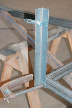
Axle
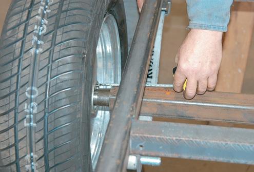
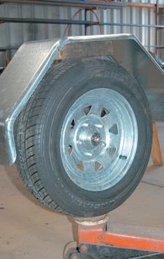
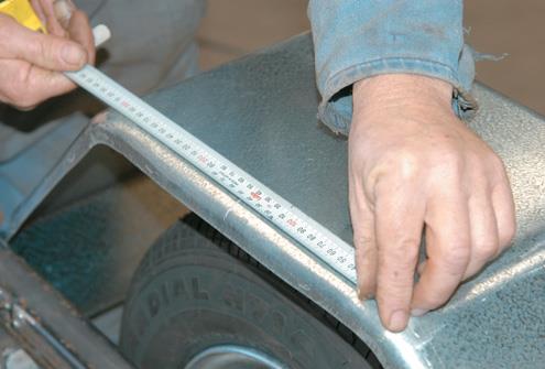
I then put the springs back on and place the axle to know where to drill a hole in the axle for the springs locator. To get the correct width for the axle RHS, put the wheel with the tyre onto the hub and axle stub, and place it in the box section. The tyre should be 50mm from the side rail. (12)
Measure the width across the trailer from spring centre to spring centre. The trailer frame is 1210mm wide, the springs are 45mm wide. So from locator pin to locator pin in the centre of each spring should be 1165mm. On one half of the axle, drill a locator hole for the pin at 582mm from the axle centre. Place the axle and measure to the other locator pin to drill the second locator hole.
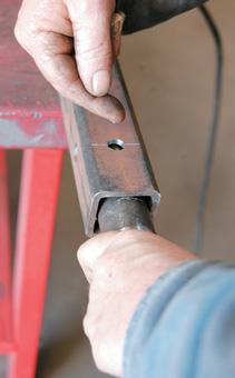
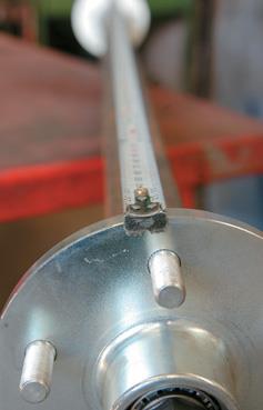
Put the axle stub in the wheel. Put it in the box section with a 50mm space to the tyre, Mark the stub with a chalk line where it emerges from the box section. When I took the stub axle out, I found the chalk line was at 70mm from the inside end of axle stub. So I drilled a hole at 50mm from the end of the box section where the weld material would enter and hold the axle stub in place. (13) This allowed for another 20mm of stub inside the box section for added strength. Make sure you turn the box section to drill a different face from the face where the spring locator hole is found.
Push in the stub axle to the chalk mark and hold it in place. Hold the stub axle fi rmly while tack welding (I use a jig but you can hold it with your hand). Hold the stub square and hard on bottom and flush against the side– you can tell when it’s firm and square against the side of the box section. (14)
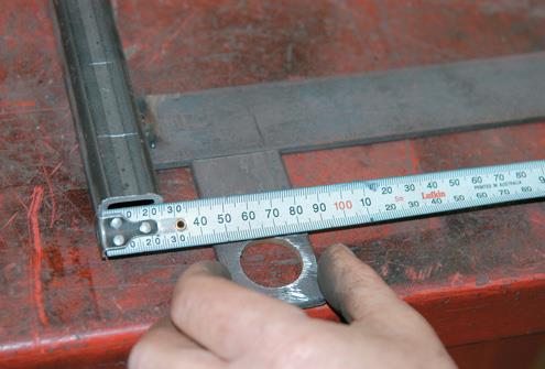
With axle stub in place, if you want to check the squareness of the hubs, assemble both and do measurements all around the circumference. The four positions should be the same and I found that the 1480mm distance checked on every quarter of the hub face. (15) I do this measuring when the stub axle is tacked only (in case of alteration).
Now weld the axle stub in by first filling the hole in the box section. When welding the axle stub, you can leave the nut on the hub to protect the thread. Weld the end of the axle box section as per the instructions for the components. The other hole in the axle is for the spring locator.
13, 14 & 15
16 & 17
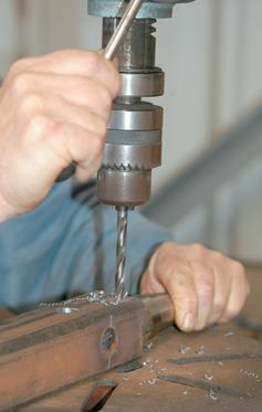
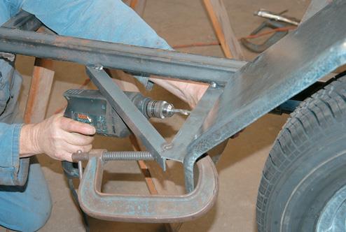
Next, I drill the holes in the axle to prepare for galvanizing. (16) Drill all the closed cross-section members with two or three holes to allow for breathing during galvanizing. The drawbar and side members of the frame are open cross sections. Normally the front and back middle members are the closed sections. I drill 4mm or 6mm holes for galvanizing.
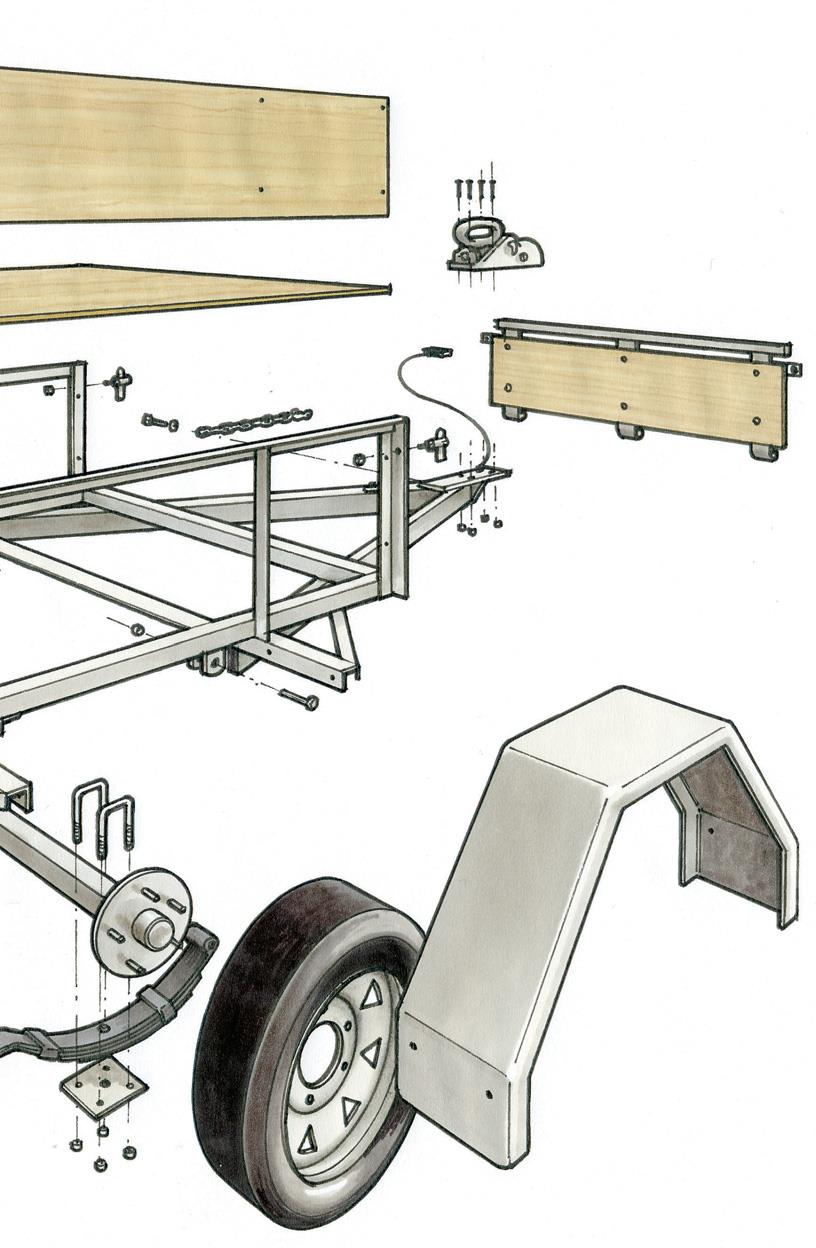
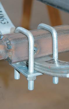
Place the axle on the locator pins and bolt it on to the springs by U bolts supplied. (17) I put the axle on top of the spring to get the trailer lower which I prefer – it looks ugly if it is sitting up at an angle to the car. (The Code of Practice for Light Trailers Standard NZS 5467:1993 3.3.1 refers to a “properly set-up” trailer).
The rating of the springs is determined by the number of leaves. The spring is strong enough to hold the axle unit and we have used springs with a weight rating of up to 1000 kilograms.
18
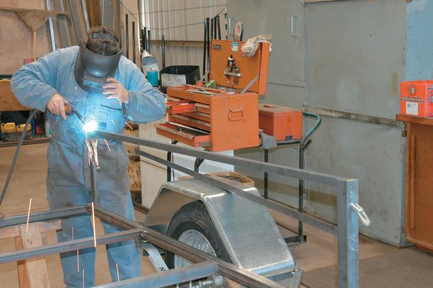
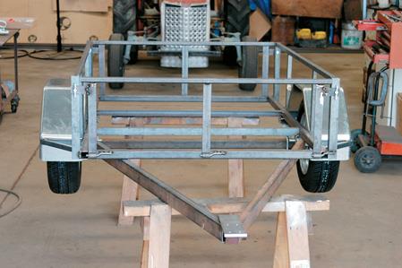
Mudguards
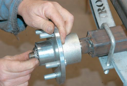
Put together the axle assembly to make sure it all fits and to get the height of the mudguards. (18) To do this put the hub and wheel on. Put 80mm clearance between tyre and mudguard – enough room for when the weight on trailer depresses the springs the mudguard does not hit the top of the tyre.
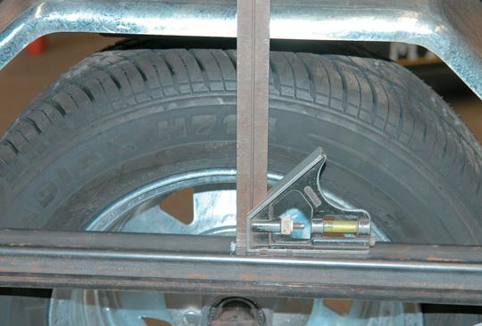
I use a block of wood on the tyre to set the gap and put a jack under the lifted trailer to stop the wheel turning. (19) Measure 900mm along the centre of the side beam to centre the mudguard. 20) Square up. (21)
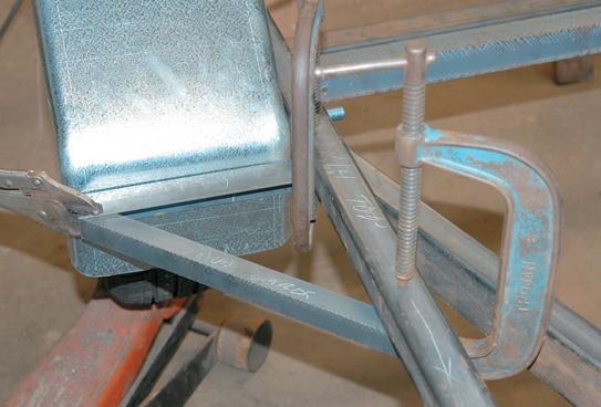
The mudguard mounts are pre-cut and pre-drilled. Clamp and weld them, and the angle mounts, underneath the side beams for strength, rather than butt weld them sitting against the side beams. (22) Always check that the mounts are square to the beam. (23) Clamp and tack weld on the mounts and the angle mounts.(24)
19
20
21
22
23 & 24
Angle mounts protect the mudguards — people driving around may run into things with the side of the trailer, or might stand on the mudguards if there are no angle mounts. They give extra strength and protect the mudguards.
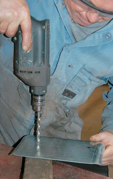
Clamp the mudguard to the mount so it is flush against the side rail. Drill through the mount holes to mark the mudguards. (25) Take the mudguards off to drill them on the bench. (26) Bolt the mudguards back on.
25
26 & 27
28
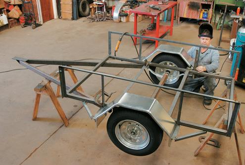
Side rails
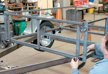
Use the 3mm-thick angle iron for the four corner uprights, and 1.6mm-thick angle iron for the uprights along the side. Pre-drill holes in the back and front uprights for the toggle bolts which will fasten the gates. I worked the height out in conjunction with the 30mm long hinges that come in the trailer components.
The tailgate and front gate will have three hinges welded and suspended from the back and front top rail. The sideboards will be 300mm from deck, but it’s not critical for the toggle to be 300mm. I pre-drill the toggle hole anywhere below the 300mm top line.
Now weld the uprights along the sides onto the beams. I do the back corner fi rst, making sure the fl ange of the angle iron is outside to receive the top rail. Clamp and check it’s square. (27) I have found a magnet square handy. Then tack weld the back upright. (28)
29
30
Do the same with the front upright, then measure the angle iron top rail to see that it fits. The top bar flange is placed so the side uprights can fi t in underneath. Clamp the top rail and tack weld it. (29) You could use box section instead of angle iron but it comes down to cost.
When you place the timber sides, leave a gap so you can tie-off on the top bar when using the trailer.
Next I place the uprights along the side. The distance of the uprights from the end of each side doesn’t matter as they are only to attach the side boards to. I locate the uprights on the mudguard mounts to add strength. Check they are square, clamp and tack weld. (30)
31 & 33
32
34
Gates
The front gate and tailgate are built in the same way. The top rail is 25mm RHS, and there are three hinge straps. The outer hinge straps have the toggle strap welded to them. The middle hinge strap is placed at the 600mm centre of the 1200mm rail. Both toggle and hinge straps are available as ready-made components, although I make my own.
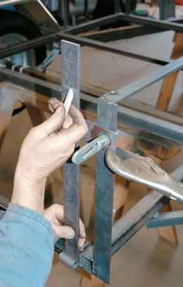
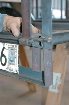
Put the toggle in the outside upright so you can measure the gates against it. Clamp the toggle strap to the upright and measure where the hinge will be cut. (31) I measured 360mm from the top of the upright to the top of the deck, less 25mm for the width of the top rail, and cut the hinge at 335mm.
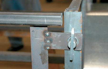
Check how far down the toggle strap is on the upright and on the hinge (32) – in my case, 45mm — and how far the outer hinges will be in from the side when attached to the toggle strap. Square the hinges against the rail (33) and clamp them on the bench. Tack weld the top of the hinges to the inside of the rail and tack weld the toggle straps to outer hinges. (34)Fit tail gate, making sure the toggle is in middle of hole in the toggle strap and will slide open off the toggle easily. Clamp the hinges to the frame at the bottom. (35) I like to make sure the hinge pins all point in the same direction, so that the gate can be slid off (when you need to have open trailer front or back for long timber, for example).
Grind away any weld obstructions smooth on the side-mounted uprights to allow the hinge pins to fi t smoothly across, prior to welding them. Put in the toggle and clamp on the toggle strap. Tack weld the hinge pins to the frame. (36)
35
36
37
The straps to support the angle iron frame that holds the number plate and lights is butt welded fl at to the side frame. Underneath the trailer tailgate, tack weld the angle iron cross bar on to the metal straps. The strap for the light assembly sits in side the flange of the angle iron and on top of the box section. (37)
To create tie-ons for ropes securing loads, bend small pieces of rod in a vice and weld two or three along the side frames. Weld two small barrels or tubular sections about a metre apart and along the inside of the side frames for the light cable. The cable will run from the inside end of the drawbar to the back of the trailer.
I now round off the sharp edges of the frame with the grinder. Before galvanizing, the trailer must be disassembled. Take off the wheels, mudguards, axle, springs, gates and coupling. Now be sure to solidly weld all the tack welds you’ve made in every joint. This is obviously for safety. But also, when you send the trailer frame, gates and axle to the galvanising bath, you need to have the welds fully enclosed. If you send it only tacked, rust gets in the gaps and weeps out in the metal when it is dipped in acid first to pickle it, and this is unhelpful to the galvanising.
In part two: After the trailer returns from the galvanizing plant, I finish the deck and wiring.
TRAILER STEEL CUTTING LIST
RHS = rectangular hollow section iron MAIN FRAME 40MM X 40MM X 3MM RHS 2 @ 1800mm (frame sides) 2 @ 1130mm (frame ends)
CROSS MEMBERS 40MM X 40MM X 5MM ANGLE IRON 2 @ 1130mm
DRAWBAR 65MM X 35MM X 3MM RHS 2 @ 1800mm (drawbar arms)
Angle support plate, front of drawbar 50mm x 5mm Flat 1 @ 150mm
Coupling plate 80mm x10mm Flat 1 @ 250mm
AXLE 50MM X 50MM X 5MM RHS 1 @ 1300mm
MUDGUARD SUPPORTS
40MM X 40MM X 1.6MM ANGLE IRON 4 @ 250mm 25mm x 25mm x3mm angle iron
Angle mounts 4 @ 350mm
SIDE RAILS
25MM X 25MM X3MM ANGLE IRON 2 @ 1795mm (sides) 4 @ 400mm (supports)
40mm x 40mm x 1.6mm angle iron4 @ 400mm (supports)
TAIL GATES
25MM X 25MM X 3MM RHS 2 @ 1200mm
TAIL LIGHT
40MM X 5MM FLAT IRON 2 @ 130mm, 2 @ 120mm
40mm x 40mm x3mm angle iron 1 @ 1210mm
PLYWOOD CUTTING LIST
BETWEEN 5-PLY 12MM TO 7-PLY 17MM TANALISED
C-D GRADE SECONDS 2400mm x 1200mm
1 @ 1760mm x 1200mm (deck)
2 @ 1200mm x 280mm (tail gate boards)
2 @ 1760mm x 280mm (side boards)