Step-by-step through an electric bike conversion
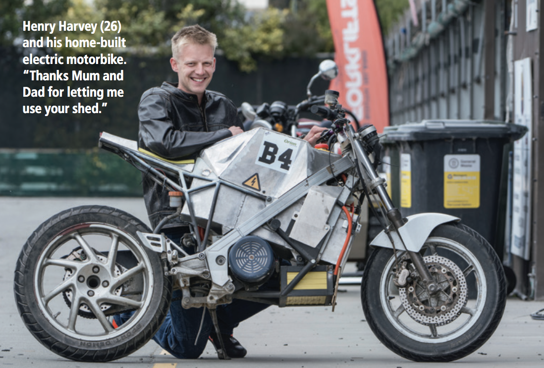
By Henry Harvey
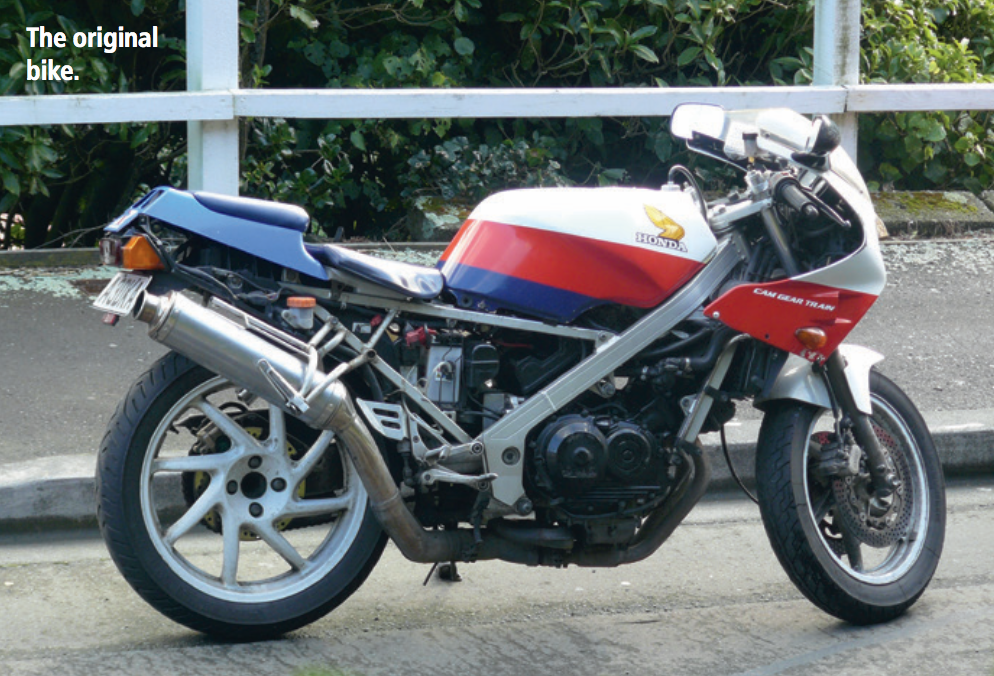
As a designer and motorcyclist, I had the idea of building an electric motorbike for a long time. The opportunity arose when I was in my nal year of an honours degree in industrial design at Victoria University. I rode a 1987 Honda VFR400 to my lectures and the bike started having engine problems. I pulled out all combustion-related components and sold them. By the time I had a plan for an electric motorbike laid out I was part- way through a post-graduate diploma in Computer Aided Design (CAD) at Christchurch Polytechnic. My electronics skills were almost nil and I didn’t know much about motorcycles either. But I’d had some part-time design work, worked as an apprentice in a workshop and I’m sort-of a wannabe engineer. I wanted the bike to show that I could do more than draw pictures and I hope it will help in my job applications.
Around this time my brother Edward was also in the process of converting a sedan to electric drive. His experience turned out to be invaluable. After selling all the parts relating to the petrol engine, I was ready to choose my major components: the batteries, motor and controller. I had to ask a lot of questions at this stage and directed many towards Iain Jerrett of Astara Technologies. Iain has built several bikes with AC motors so his experience was very helpful. In order to make considered decisions, I narrowed my use scenario. The bike was going to become a torque- happy commuter, capable of highway speeds but designed for city use. This was mainly driven by economics. A long-range vehicle would require more batteries, increasing cost while also making it more dif cult to t them in the relatively small aluminium motorcycle frame. Based on these restrictions I ordered the main components.
Batteries
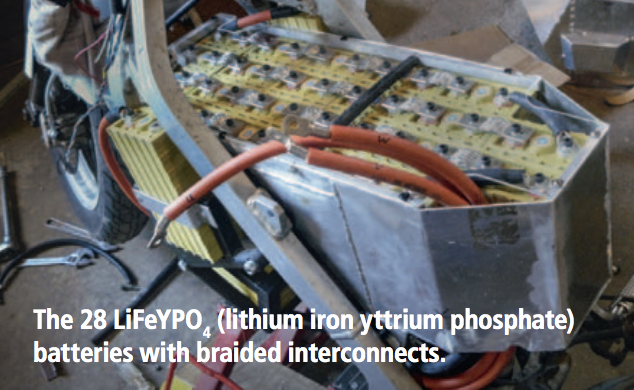
For batteries, I chose 60 Ah Winston LiFeYPO4 (lithium iron yttrium phosphate) cells, which I ordered from EV Hardware. This brand has been used in a lot of conversions and while there are other more energy-dense batteries, Winston are well-known and reasonably priced. While lead acid batteries would have been cheaper up front, their short lifespan and poor energy density ruled them out. Because I had decided on a 72V system, I chose to use 28 cells. 3.2V per cell makes a series connected pack of 89.6V nominal. Although this is above 72V, it is not an issue as long as the controller is rated to handle it. Voltage “sag” occurs at high current draw so a higher voltage pack is a necessity for good performance.
Motor & Controller
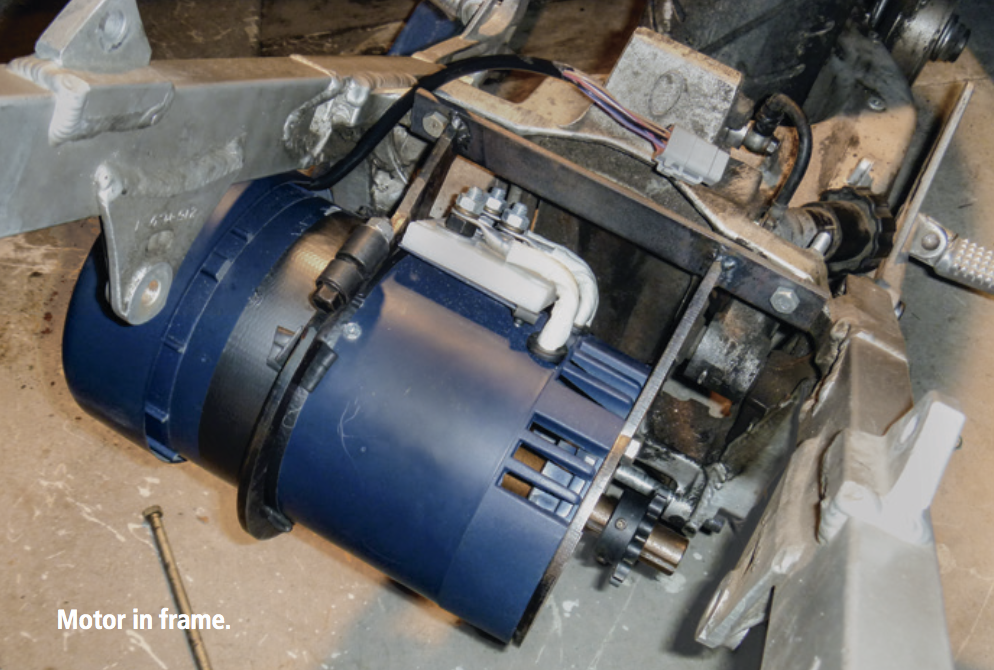
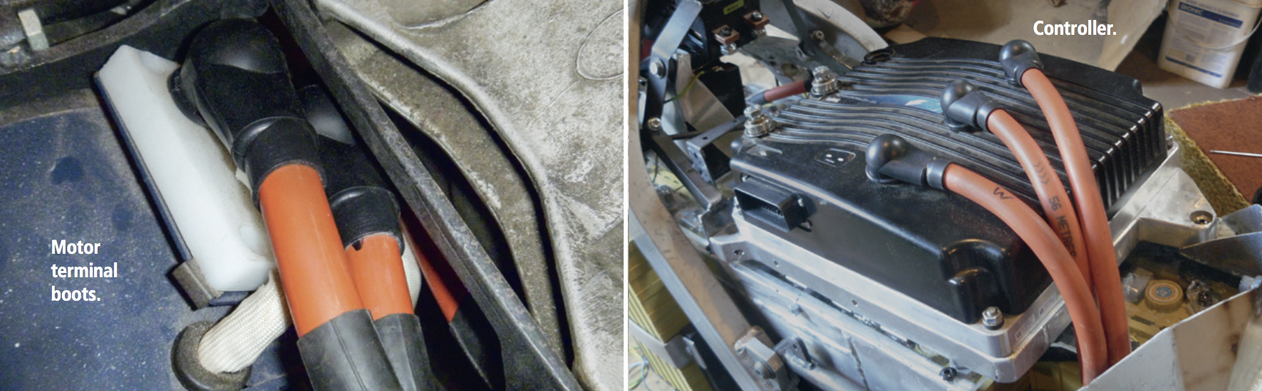
As an electronics novice, I chose the safe option of buying the motor and controller as a kit from Astara Technologies motor is a HPEVS AC15. This is a 72V AC motor, rated to produce 68ft/lbs (93 N m) of torque and makes 27HP at 7500 rpm. The controller is a Curtis 1238. It is capable of delivering 550A for short periods. These controllers are very programmable but this generally requires a handheld programmer or computer software which is an additional cost. It is frustrating that Curtis doesn’t include a USB programming cable with the controller, although Astara Technologies offered me the use of their programmer.
Charger
The charger was another important component which needed to be bought after I had decided on which batteries I would use. I chose an Elcon 1500W charger with a charge curve programmed specifically to my batteries, with charge curves programmed above and below my cell count, in case I chose to add or remove cells. Other specialty components included DC fuses, contactor, emergency disconnect, state-of-charge meter, battery interconnects and many more. I also required a DC-DC converter, which allows me to drop pack voltage down to 12V, for the motorcycle’s standard low-voltage system.
Battery monitoring
I chose not to include an individual cell- monitoring system in my circuit as my battery pack would be bottom-balanced. All cells in a series pack have slightly different capacities. Because of this, they can’t all be expected to reach their full charge/discharge level at the same time. Bottom-balancing moves the cell imbalance to the top of the charge cycle where damage is less likely to occur. One of the easiest ways to damage a cell is during discharge when the weakest cell reaches 0V before the other cells. When this happens, the other cells will continue driving current, which effectively reverses the cell potential of the 0V cell, destroying it almost instantly.
When charging the pack near the end of the charge, cell voltages will be different. However, usually the charge current is ramping down at this stage anyway, and the voltage of the top cells will start going up quite fast, which raises the pack voltage relatively quickly to the point of charge cut-off.Generally it is quite safe for LiFeYPO4 batteries to reach up to 4.0V at the end of their charge cycle, as long as the charge current is not high and they are not held at this voltage for long periods of time. Bottom-balancing isn’t fool- proof. However, it can remove the need for expensive (and sometimes failure- prone) battery management systems (BMS). I made my decision based on recommendations and my own research. I will continue to check my batteries periodically and I am not yet in a position to endorse this method.
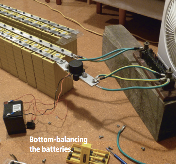
Bottom-balancing
To bottom-balance my batteries, I used aluminium strips with bolt holes in them to join the terminals in parallel. I placed a load across the circuit in the form of a large resistor element. Using a 12V contactor with a small battery, I could switch the circuit on and off. I placed a fan in front of the element to dissipate heat. It took around seven hours to bring the batteries down to 2.7V. Nearer the end I was constantly checking the voltage of batteries at either end of the pack. Several times I left the circuit off for 24 hours to allow the batteries to settle.
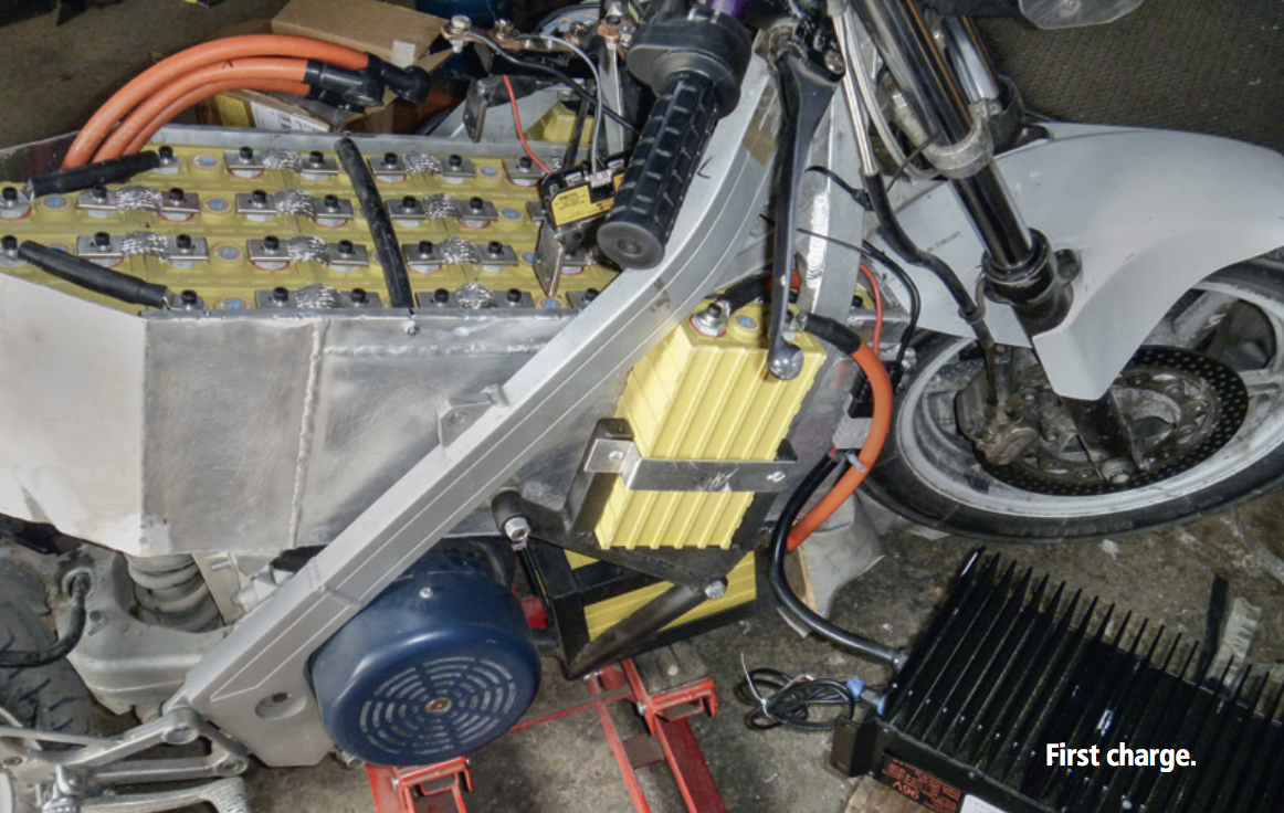
The first time the batteries are charged in series they need to be carefully monitored to make sure none of the batteries are of significantly lower capacity which could cause overcharging to that battery. Then in theory the batteries can be charged and discharged safely.
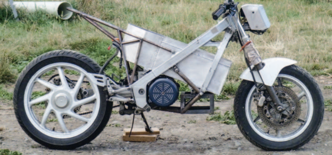
Motor
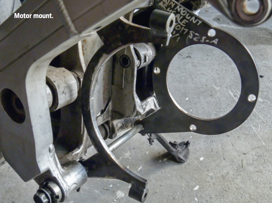
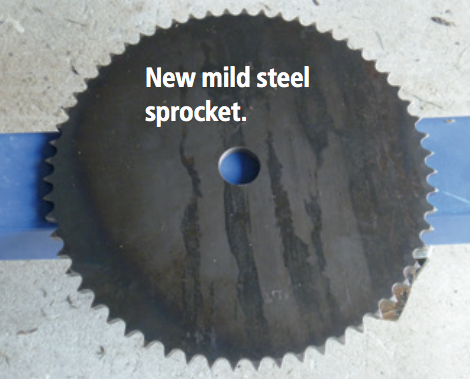
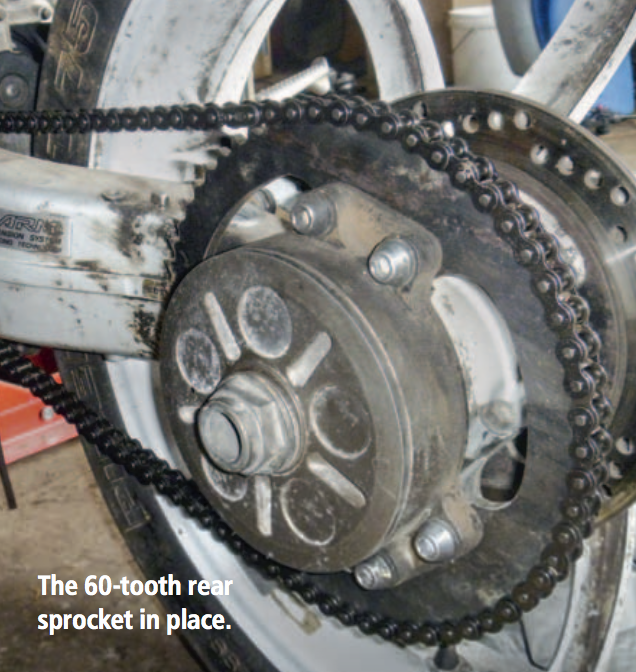
After I stripped away all combustion engine-related parts, my first task was to mount the motor. It should be as close as possible to the swingarm pivot. As suspension sag affects chainline, I tried to match the new sprocket position in the vertical axis to the original sprocket position. I modelled the parts on a computer and got them profile cut from 6 mm mild steel. Milled aluminium would be lighter and look nicer but at the time I decided mild steel would be easier for me to work with and cheaper. Because my bike uses a single-sided swingarm, my sprocket options were limited—the swingarm bulge prevents a large sprocket being used. I knew from research that I wanted to get a drive ratio of about 1:5. This would give me a top speed of around 140 km/h and hopefully good torque. This meant that I had to use a 428-pitch chain to achieve a smaller rear sprocket diameter.
I theorised that because the bike had smooth power delivery and no gears, this pitch would be strong enough. I used a 12-tooth off-the-shelf sprocket for the front—any smaller and it is arguably hard on the chain and sprocket. This meant I needed a 60-tooth rear sprocket which I had to buy as a blank and get the hub pattern machined out. This was quite an expensive process for the sake of a fancy swingarm.
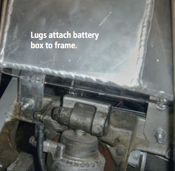
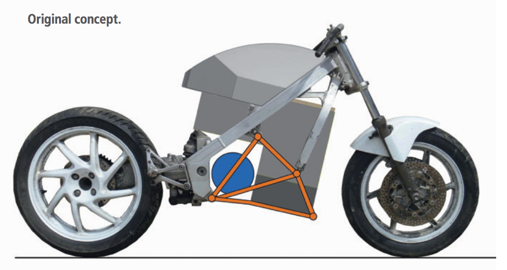
Fitting batteries
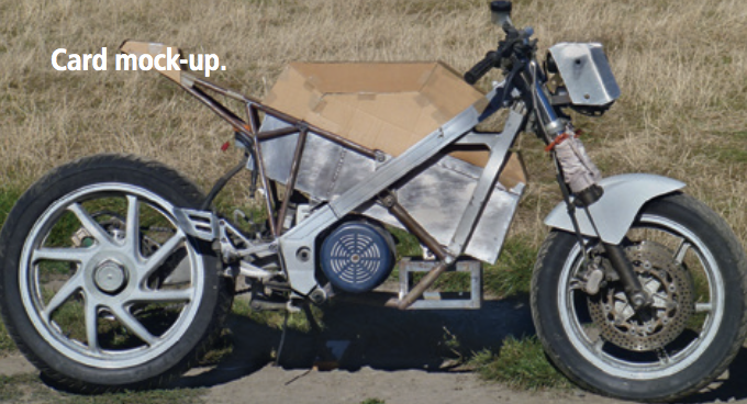
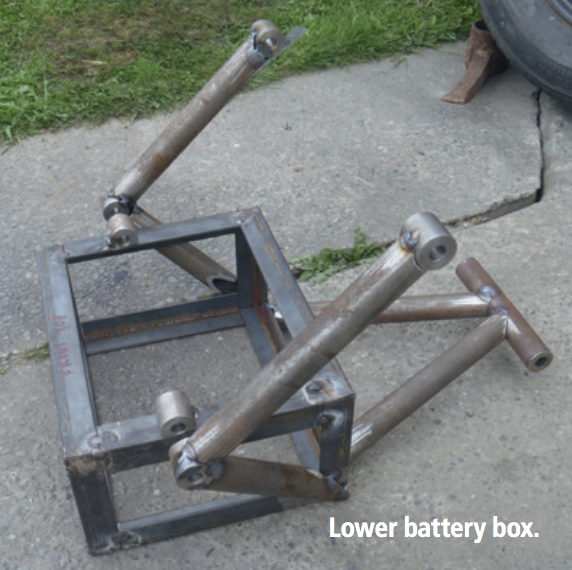
Once the motor and sprockets were mounted I had the most difficult spatial task of the whole project: fitting 28 batteries in without the bike looking like it’s made of Lego. After a lot of cardboard and wood mock-ups and one failed aluminium box, I finally found an acceptable solution. I decided I needed to still be able to have horizontal bracing through the centre of the frame, where the motor was once bolted. This limited my options and meant that I had to have two main boxes. The lower is made from angle iron and the top is 2 mm aluminium. The original box was made by a tradesman but in the end I had to cut it up and re-weld it myself after my plans changed.
The tubing that makes up the new stressed member is BS3059 boiler tube with an outside diameter (OD) of 25.4 mm and a wall thickness of 2.90 mm. The main fixing points are made from mild steel round bar, bored to t 12 mm, high-tensile hex-head bolts. I think it’s fair to say that it’s overbuilt. Most of the welds are TIG. I purchased an AC/DC welder specifically for the project and it is fantastic being able to weld aluminium as well as steel.
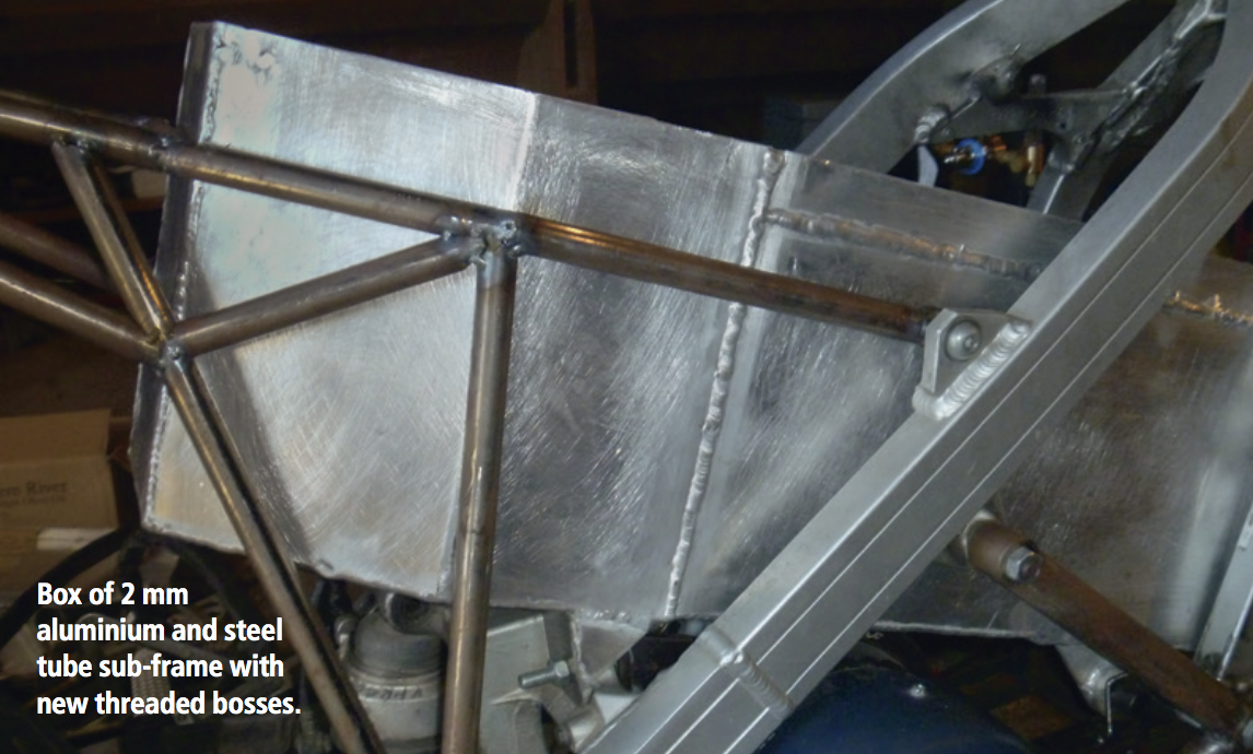
Sub-frame
The original sub-frame was made from box section steel tubing. I decided to design a new sub-frame mainly because the old sub-frame would have needed to be heavily modi ed to t around the battery box. It also had many bosses and tabs for things like fairings and exhaust that I no longer required. The new sub-frame is made from 26 mm OD mild steel tubing with 1.6 mm wall thickness. I wanted to utilise lightweight tube with good triangulation design to create a minimalistic trellis structure. I had to make new threaded bosses for my sub-frame.
I turned down some mild steel bar on the lathe then bored and threaded four M10 x 1.25 thread bosses. My old South Bend lathe was used regularly throughout the project and has been a great timesaver as I live an hour from any machine shops. The high-quality tap was rather expensive but will be used again. The sub-frame was tacked and welded with TIG. It can be a bit tricky tacking with this welding process but with enough clamps and jigs it is possible. I found that my right-angle magnet totally destroyed my TIG arc and later found this is called “arc blow”.
Welding
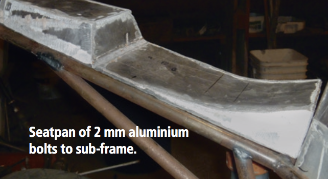
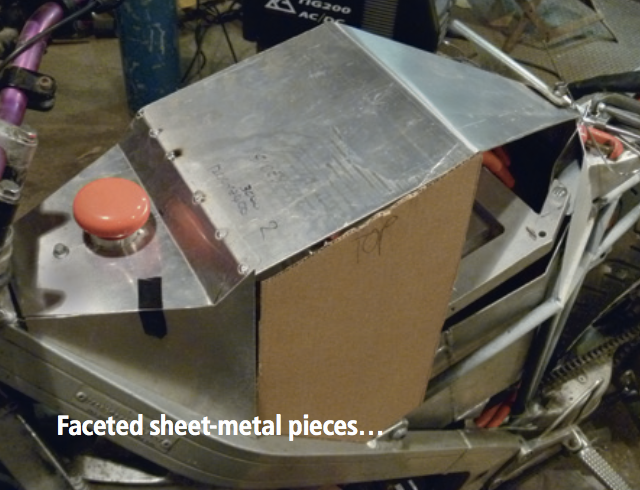
Unless you are willing or able to make an accurate jig, it’s best to tack and weld the sub-frame while it is bolted in place. It allows you to have a better idea of how it ts visually but it also helps prevent the sub-frame warping out of shape. This can be further avoided by tacking tubes uniformly and evenly around the joins and also evenly on each side, jumping back and forth to even up welding stresses. First, I tacked up the main tubes to check seat height and angle—I carefully sat on the sub-frame and checked the ergonomics and made any necessary changes with a touch of the cutting wheel and another tack. I wanted the main line of the sub-frame to run parallel to the battery box for visual uniformity. This meant a compromise of seat angle. It is really too steep to be comfortable and this issue is remedied later on with the curved seat pan. The main practical change I made to the sub-frame is a faceted sheet- metal piece that will become the start point of the new “tank” and double as a mounting point for the controller.
Auxiliary battery
For safety purposes I needed a separate auxiliary battery that would run my lights in the event that the high-voltage system failed or had to be shut off. I used a 4.5Ah SLA (sealed lead acid) battery and made an aluminium cradle for it with mount points allowing it to be bolted inside the frame. The next step was to mount the controller and the rest of the high- voltage components. The controller weighs about 6 kg and has a large aluminium heatsink. It can be run with passive cooling but I wanted the option of liquid cooling if I chose to start playing with performance settings. Initially I set up an aluminium furnace with some old bellows and I tried to cast a plate myself with the path already in it. Then I would just need to pay someone to skim it. I couldn’t get a clean pour with such a large shape so I got some 20 mm alloy plate at the metal recyclers and got a coolant path milled in it. Because I had to spot-fill some holes to prepare it, this made it difficult to mill. It is currently just bolted to my controller but later it will be sealed with gasket cement and have coolant forced through it with a simple radiator and pump system.
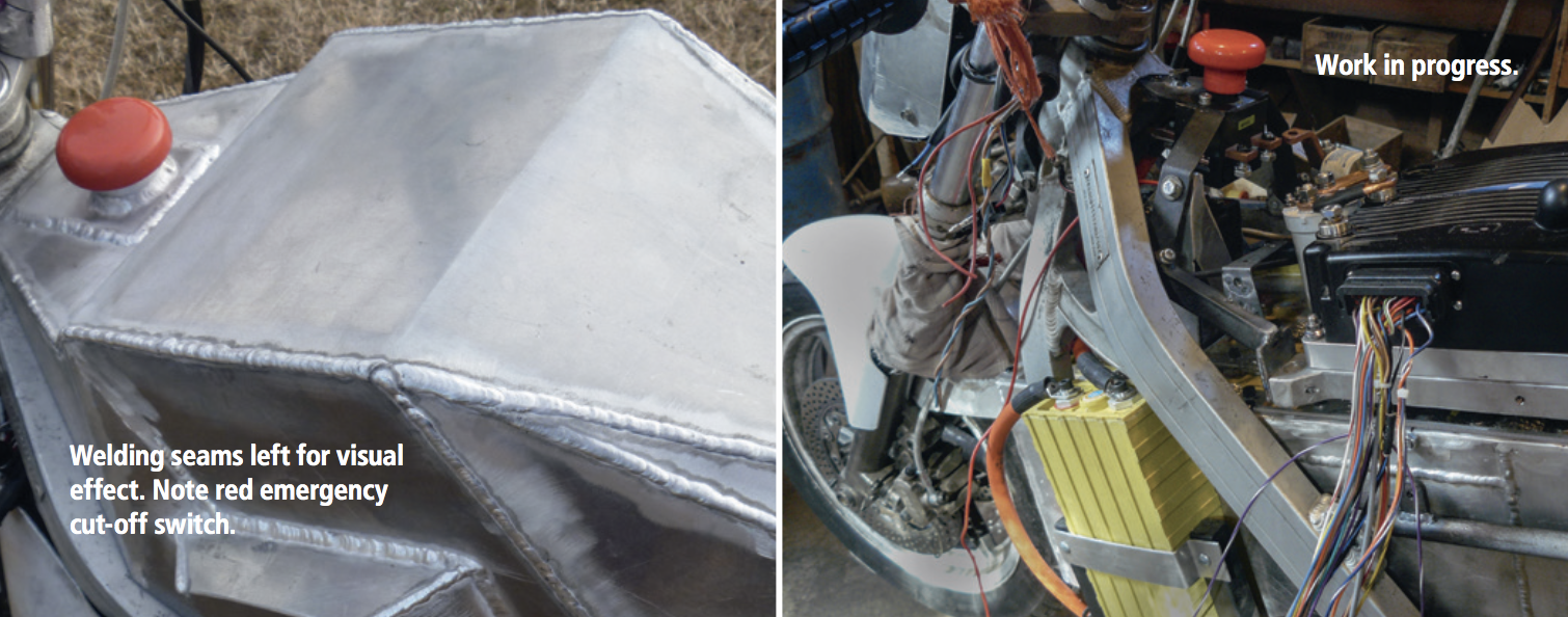
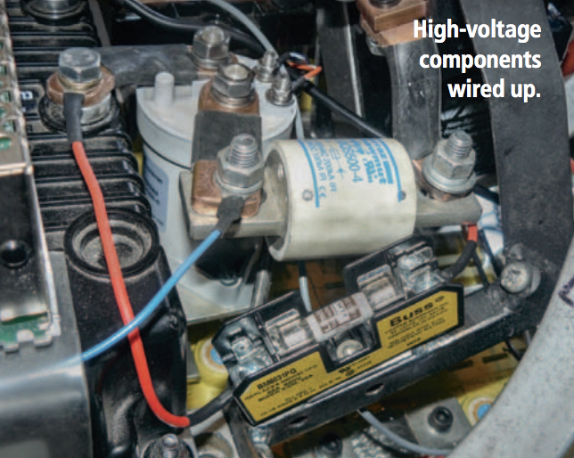
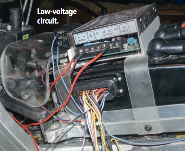
Using the previously mentioned sub- frame mount point and some frame mount points, I designed a steel framework which supports my controller plate and the other high voltage components including fuse, double pole disconnect, contactor and shunt. I found it quite difficult to t these components in safely and neatly due to space constraints. The emergency disconnect had to be located centrally and forward to allow easy operation in an accident. It is basically a mechanical push switch that requires manual reset. Because it has to hold and break high currents on both poles, it is accordingly large. The high-voltage components between the controller and emergency disconnect are joined electrically with copper bus bars which I found at the metal recyclers and bent and drilled to t. Once these components were in place I heat-formed some 6 mm acrylic to cover the bare terminals and separate these components from the low-voltage components to be mounted above. I think 6 mm was probably too thick, but it allowed me to tap threads for mounting small components. Here I mounted my 12V relays and my six-terminal blade fuse box. I heat formed some 2 mm acrylic mounts to t over the middle of the controller to mount my DC-DC converter. It is rated to drop my pack voltage down to 12V. I adjusted it to 13.7V so it would also charge my SLA auxiliary battery.
Tank
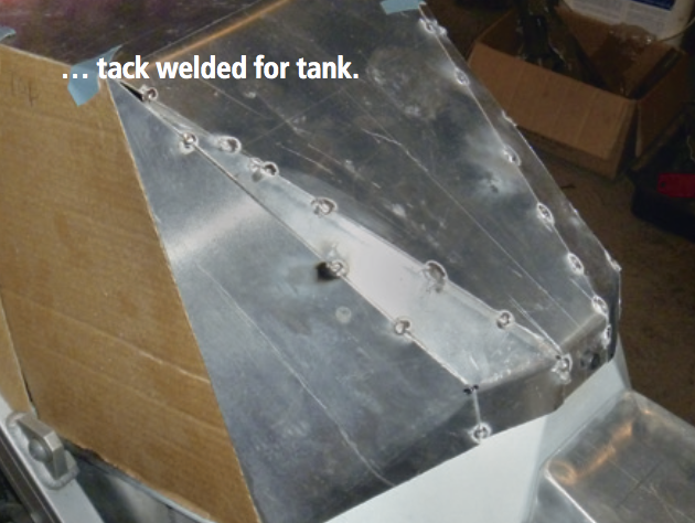
Once all my components were placed I began designing and building a new “tank” to replace the old tank which was rusted and did not t with the new square-edged aesthetic. I started sketching over photos and then moved to cardboard mock-ups. Next I cut the pieces from 2 mm aluminium, tacking them in place after ensuring mirrored faces were identical. As I went, I drilled and welded suitable mount points.
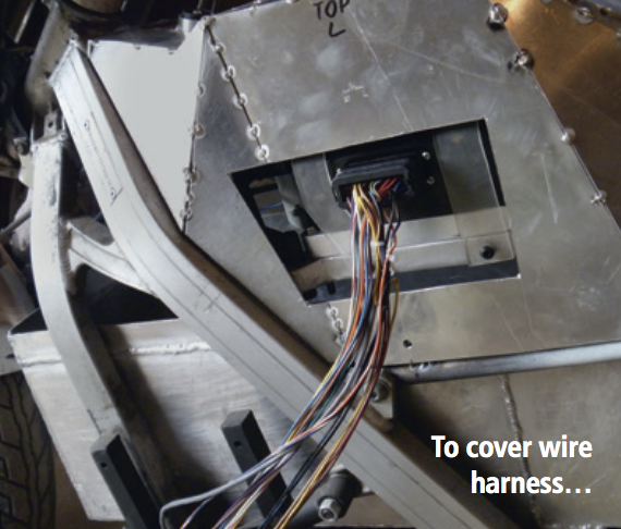
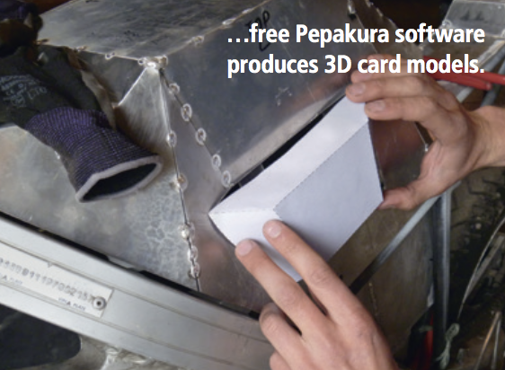
I knew that during final fitting I would have to cut into the tank and reform some surfaces to accommodate my wiring harness plug and one corner of the controller. I was happy with this as it ts with the boxy, utilitarian theme I was following. Once the tank was fully tacked, I welded it while it was bolted in place. Although my welds are not that pretty, I decided not to grind them back as I didn’t want seams cracking in the future. I also like to see welding left if possible, as to me it adds interest to a project. For some parts of the tank I used free software called Pepakura, which allows 3D models to be converted to box nets in order to print and fold paper or card mock ups. The seat pan was made with a similar process to the tank except that I ground all my welds off to improve comfort. It has a temporary foam pad which will be replaced by a thicker seat.
Circuits
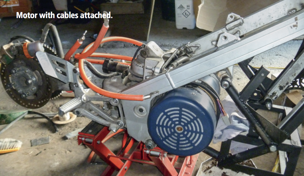
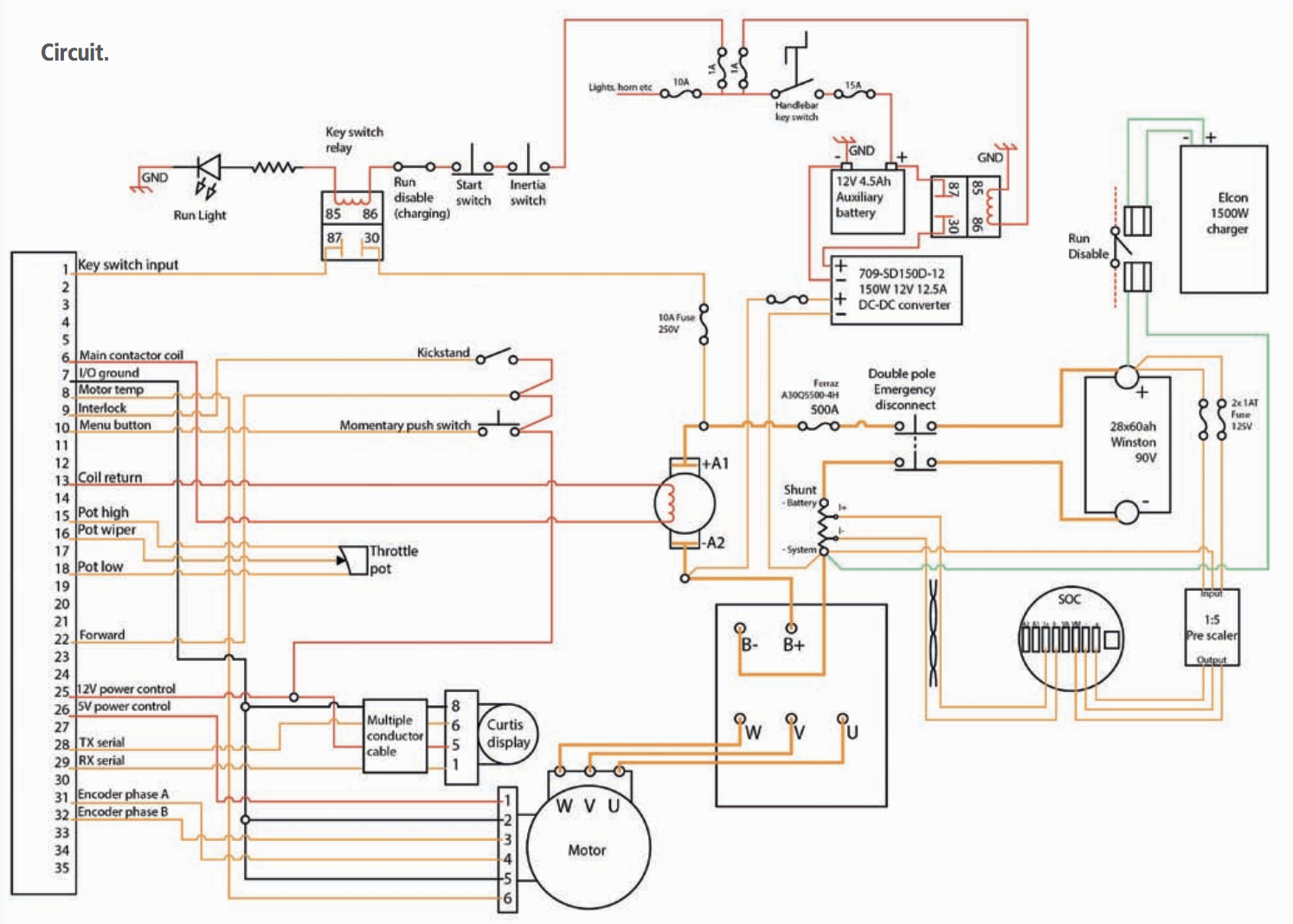
Once all the components were placed and major parts fabricated, it was time to wire my high and low-voltage circuits. I drew my own circuit diagram and committed a lot of time in the hope others would find it understandable. I used 50 mm2 cables between motor and controller and also between battery packs. This is sometimes called welding cable and it has an inner and outer sheath. I used a hydraulic crimping tool to crimp terminals onto this thick cable.
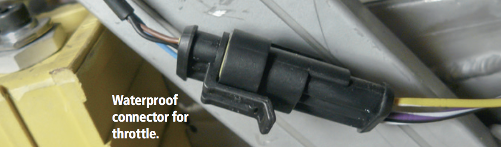
To connect individual batteries I used braided copper interconnects. These have some ex in them which may prevent fixing bolts coming loose through vibration. For the low-voltage circuit, I followed my circuit diagram carefully and used heat-shrink for all my connections. The key is to take your time and make sure you have a good range of connectors and wire. I used weatherproof AMPSEAL connectors where components might need to be removed from time to time and where rain might reach.
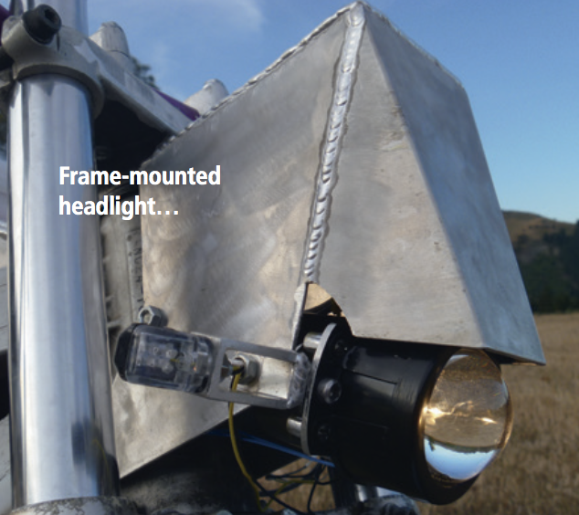
Headlight
I was initially intent on using an LED headlight on my bike to conserve energy. A good LED headlight will draw around half the current of a halogen bulb and will last longer. There are many cheap options around but reliable e-marked LED units such as Truck-Lite are still out of my price range, although prices are dropping steadily. I opted for a halogen projector light in the end. It is one of the smallest lights available and uses a solenoid to move a curved mirror to switch from low to high beam. I could have mounted my light to either the forks or to the front of the frame. I opted to frame-mount my light as it means that there are fewer wires moving and being stretched as the forks are turned.
I also chose to mount my front indicators near the headlight along with two interfaces; the TBS battery management display and the Curtis display which shows motor RPM, motor temp and more. I used sketches, card models and finally 2 mm aluminium to design a unit to support and protect these parts. I didn’t have a hole-saw big enough to cut the holes for the round displays so I had to use a lathe. Its square design has profile lines which match those of the forks.
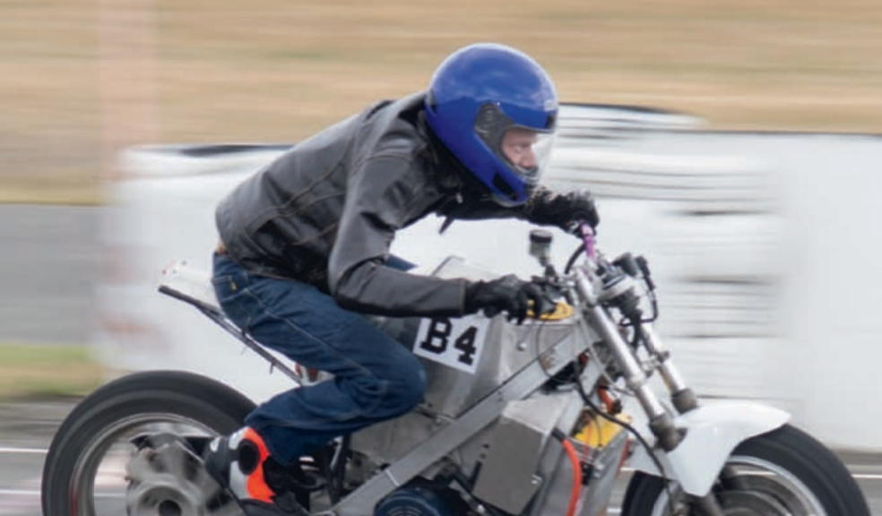
Thrilling
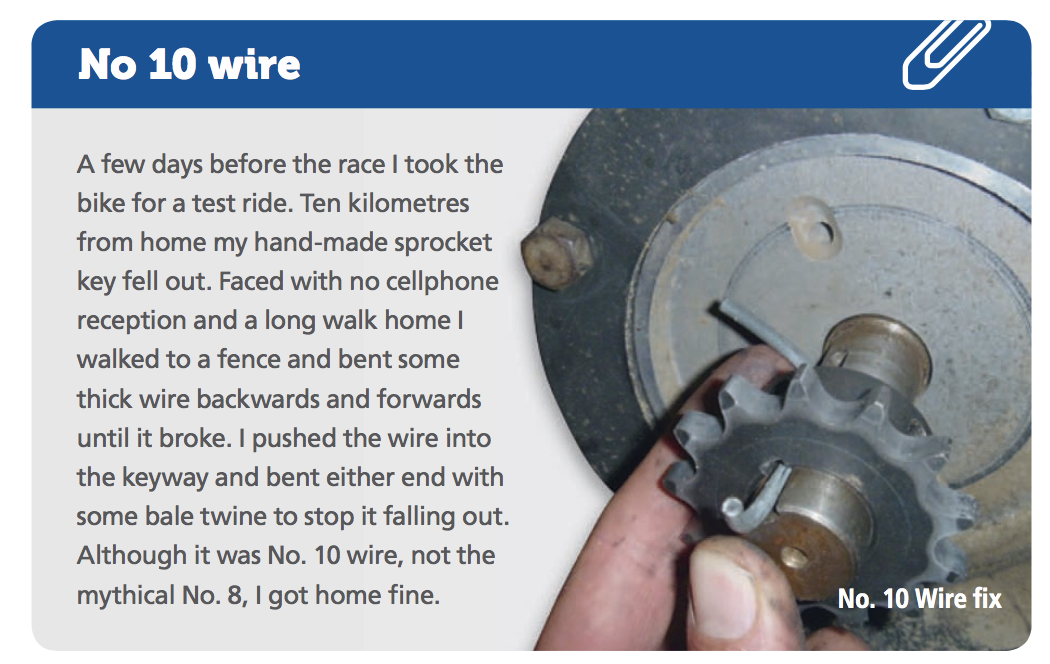
My first test ride was thrilling to say the least. Having one gear all the way up to the gearing limit of 140km/h and torque available whenever I want it is a feeling that I can’t describe. Part of what spurred me on to get the bike rolling was the then-upcoming electric motorsport event called Evolocity, held in Christchurch. I bought a proper key and took the bike to EVolocity, which was an incredibly enjoyable experience. I was able to test my bike against electric bikes on Ruapuna Raceway, as well as see many other amazing electric vehicles on the track and in the pits. My bike came second in the drag event but I was slow on the circuit due to inexperience. Next year I’ll put some practice in.
The bike is now very close to being ready for certification. A light is needed to illuminate the number plate, wiring needs to be tidied up and a few cover plates made for exposed components. I am going to use RFID instead of a key to start the bike and this will be done with an Arduino board. The final task will be stripping the bike right down and repainting the frame, sub-frame and wheels. The aluminium parts will be left with their natural finish. I had support and advice from many people during this project but would specifically like to thank Edward Harvey and Iain Jerrett. Also thanks Mum and Dad for letting me use your shed. For questions about the bike please get in touch at [email protected].